
Lotus E21 construction report part 27
Wheel design, wheel nuts and a real premiere: the first time I designed a working rear light.
The wheel nuts are a pretty simple. Indeed, I was not able to include the female features for picking up the wheel gun adapter. However, one wheel nut consists out of fife elements. Basically it is only two cylinders and a conical frustum. The wheel hubs are fixed to the rims on order not to lose them during a pit stop (this system was introduced in 2012 I think).
The wheel design was a lit le bit tricky. I needed three approaches to get them done:
1. The first approach (with white paper – because I was not able to find structural cardboard in the correct colour) was designed as medium size wheels. Page 44 of the 2013 FIA Formula One regulations:
12.4 Wheel dimensions:
12.4.1 Complete wheel width must lie between 305mm and 355mm when fitted to the front of the car and between 365mm and 380mm when fitted to the rear.
12.4.2 Complete wheel diameter must not exceed 660mm when fitted with dry-weather tyres or 670mm when fitted with wet weather tyres.
My wheels were designed with 33mm at the front and 37mm at the rear. I made a dimension check with the finished rim cylinder (without spokes). There, I detected, that the rear axle was about 4mm and the front about 3mm too wide (max. 180mm). So this design was dumped in a very early stage.
2. For the second approach, I found a cardboard, which has almost the correct colour. However, the rims are covered with a thin paper in the correct colour. In this approach, I designed the wheels to the minimum allowed distance. This time I made it to the complete rim with spokes, followed by another regulation test. To my astonishment, the car was to wide by 9mm at the rear and 7mm at the front.
The reason for this was, that the spokes collided with the brake calipers, so I had to redesign the whole cross section of the rims. One of the largest design faults I’ve ever done…
3. For the final approach, I redesigned the whole cross section with highest care and to the minimum dimensions permitted. This approach finally works and the car should be just within the regulations by less than half a mil.
At the moment I am waiting for the OZ logo which my dad is reworking it graphically (the logo is bent around the rim radius and I do not have a powerful photo tool to do this). Most of the tires are also finished and only waiting till the rim is lacquered.
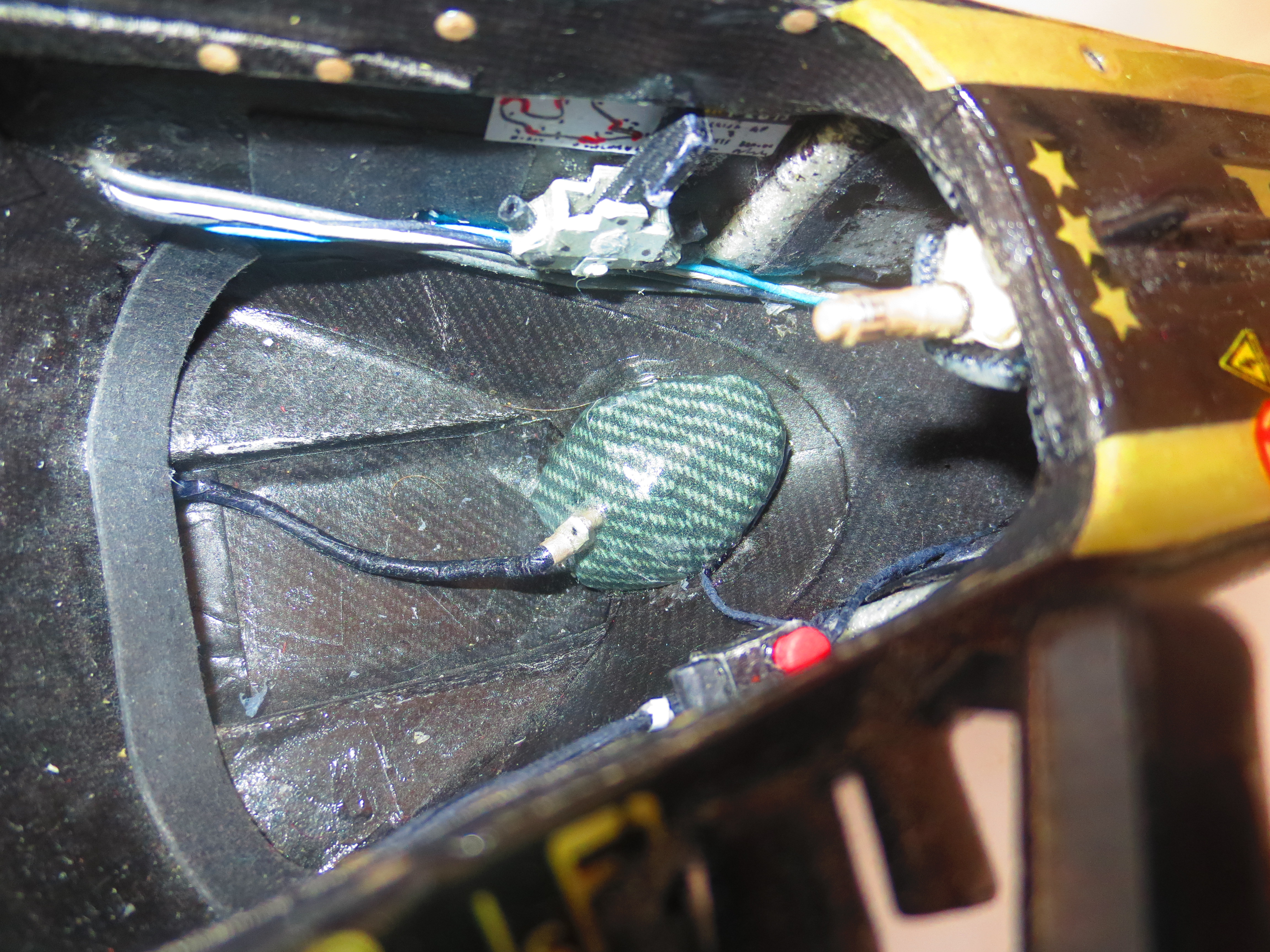
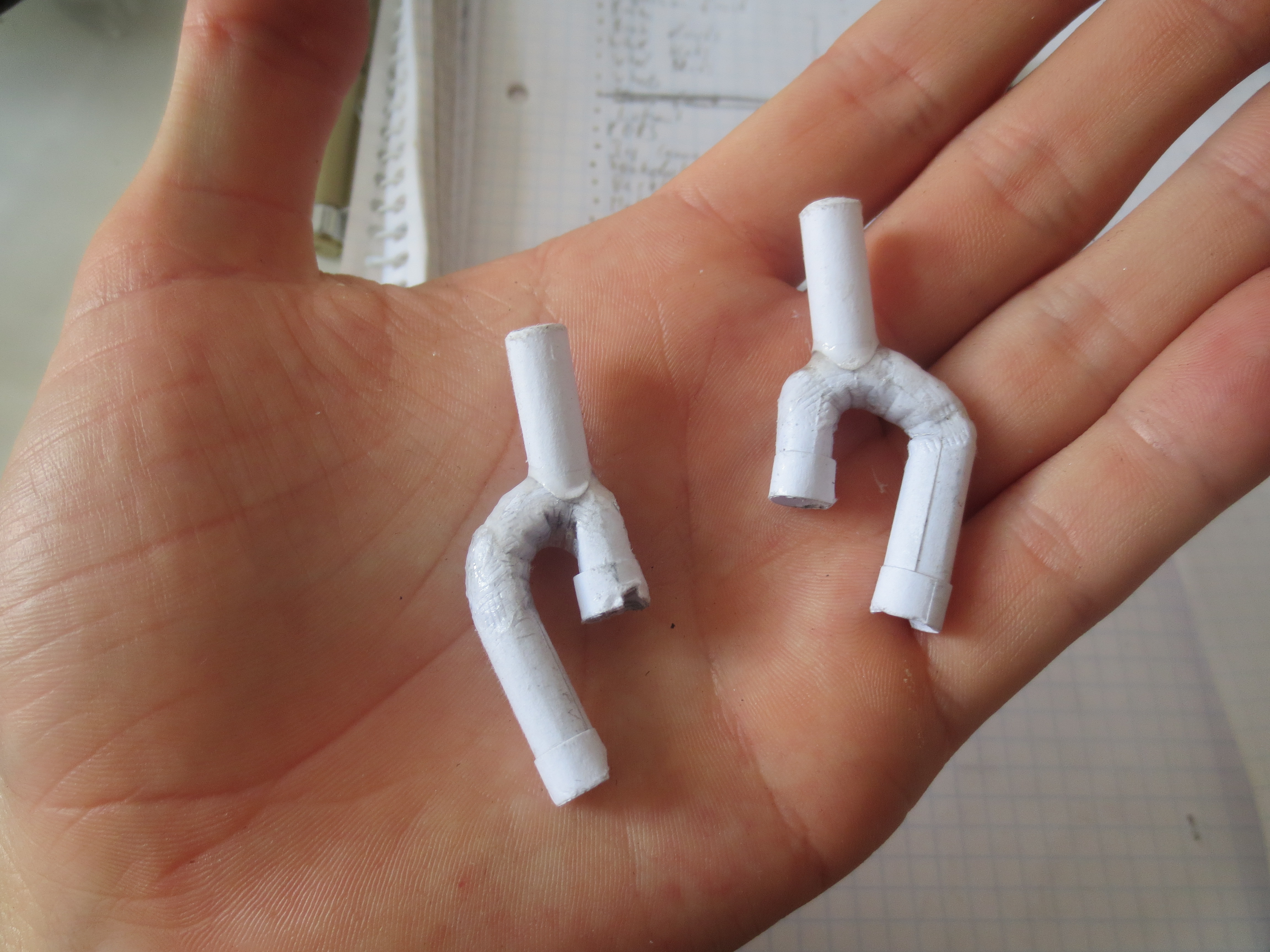
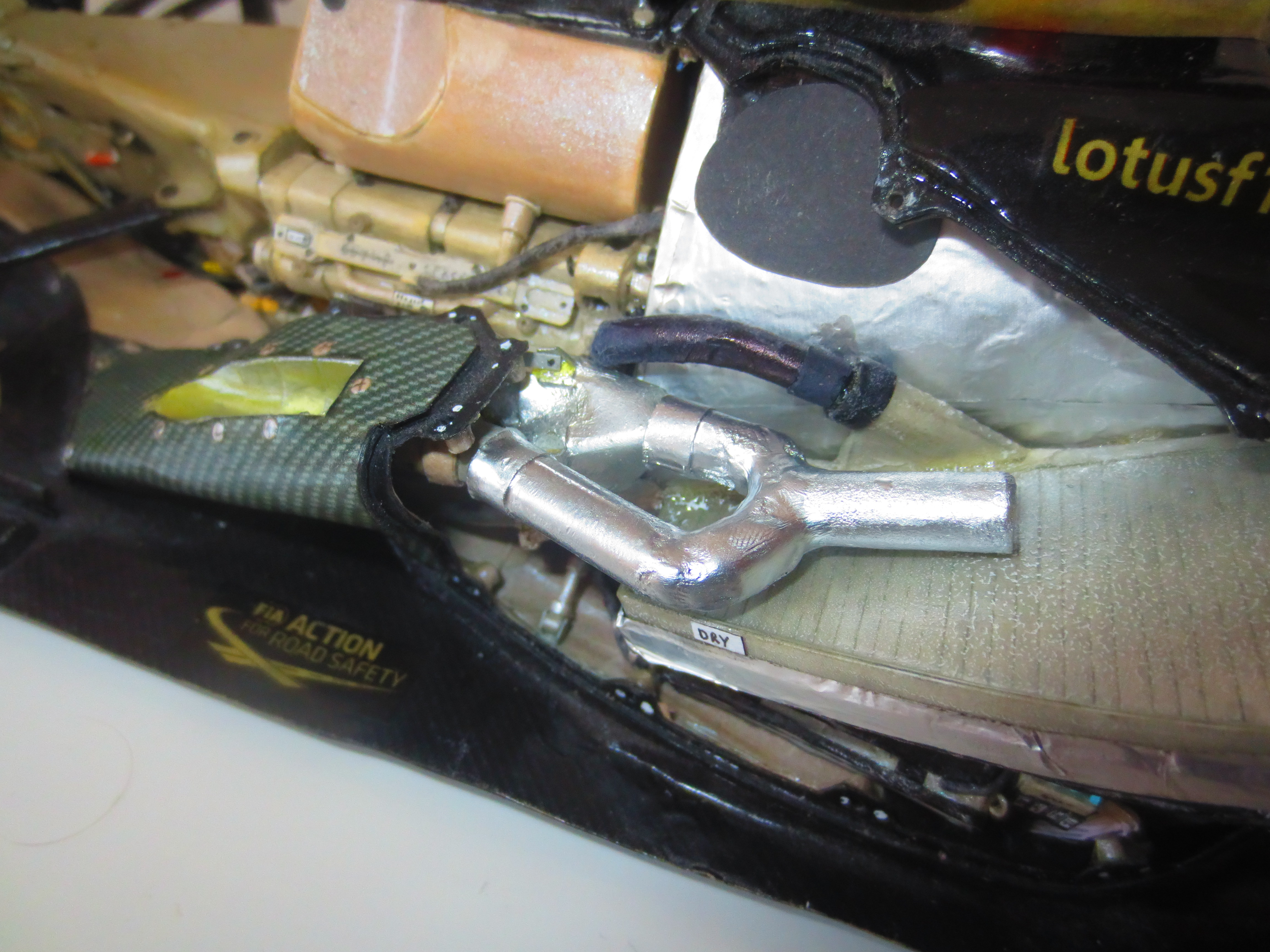
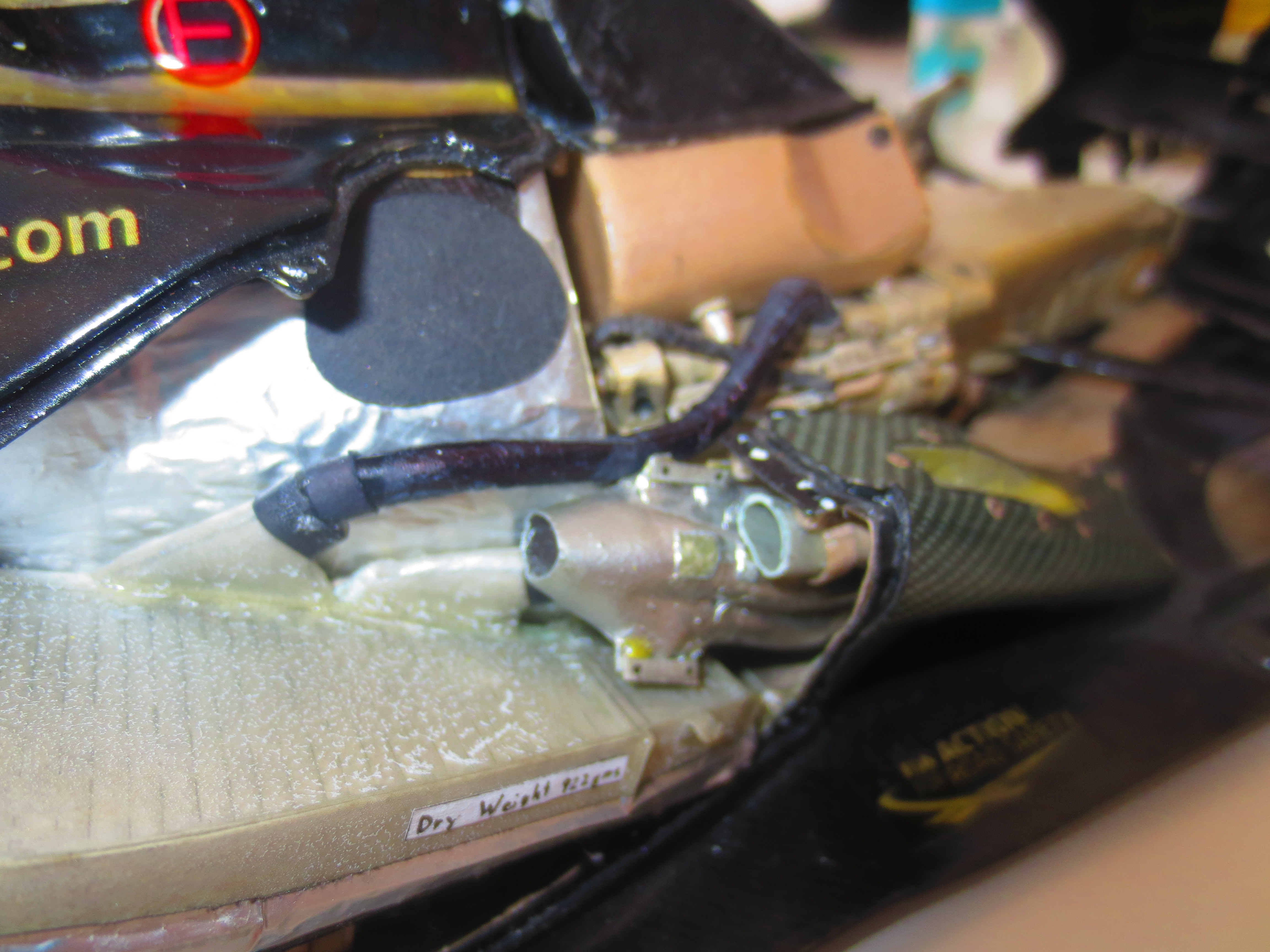
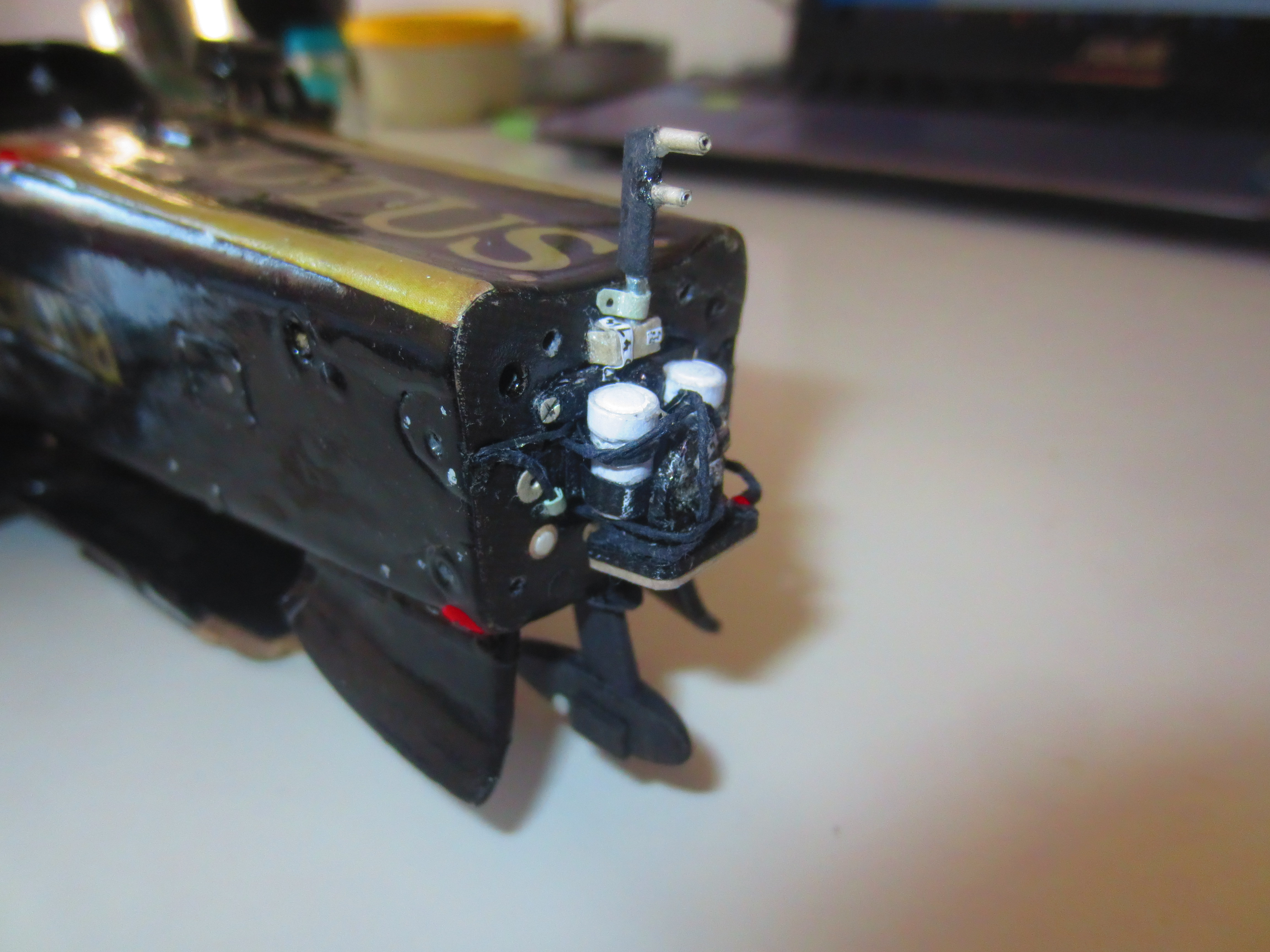
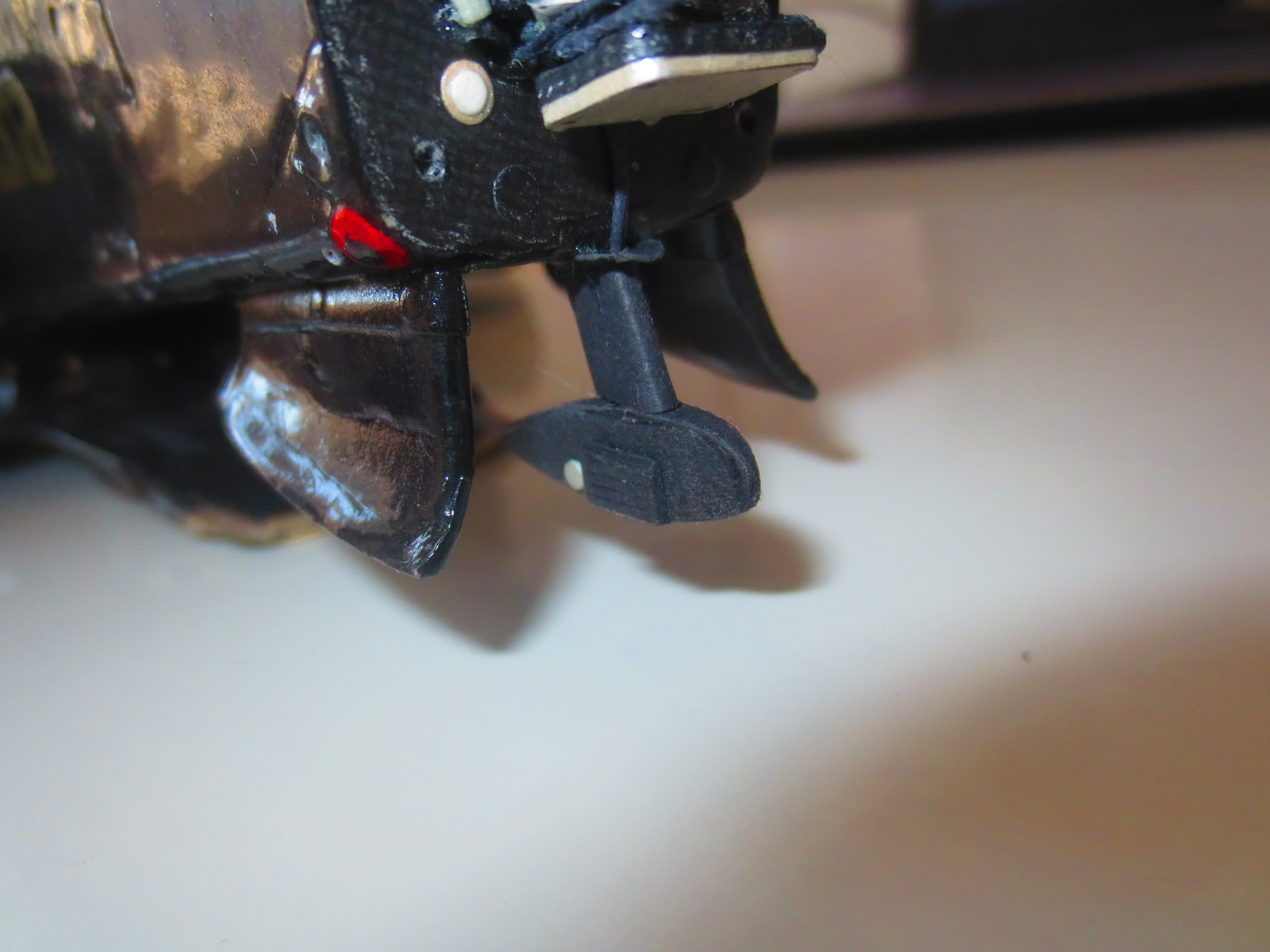
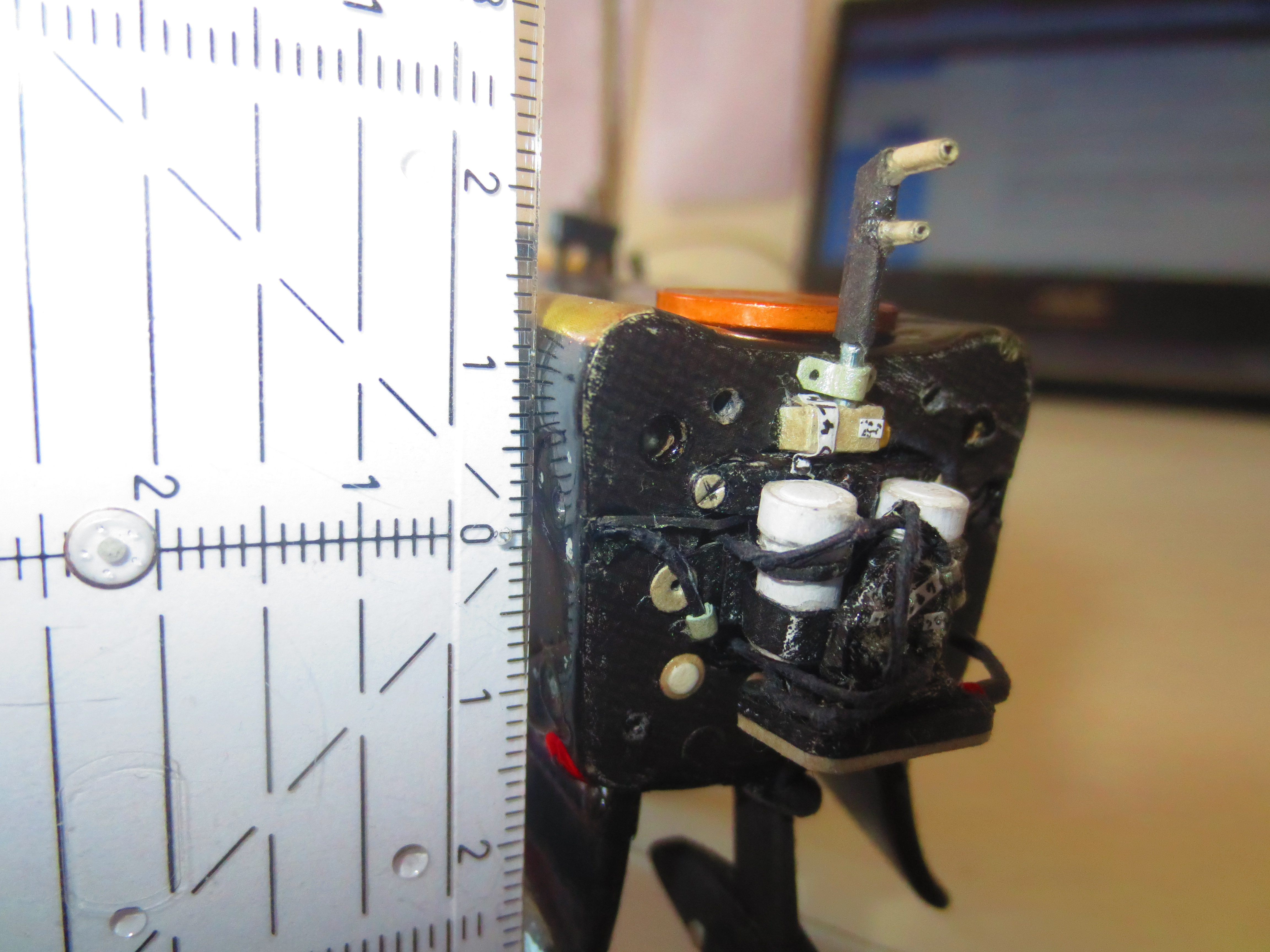
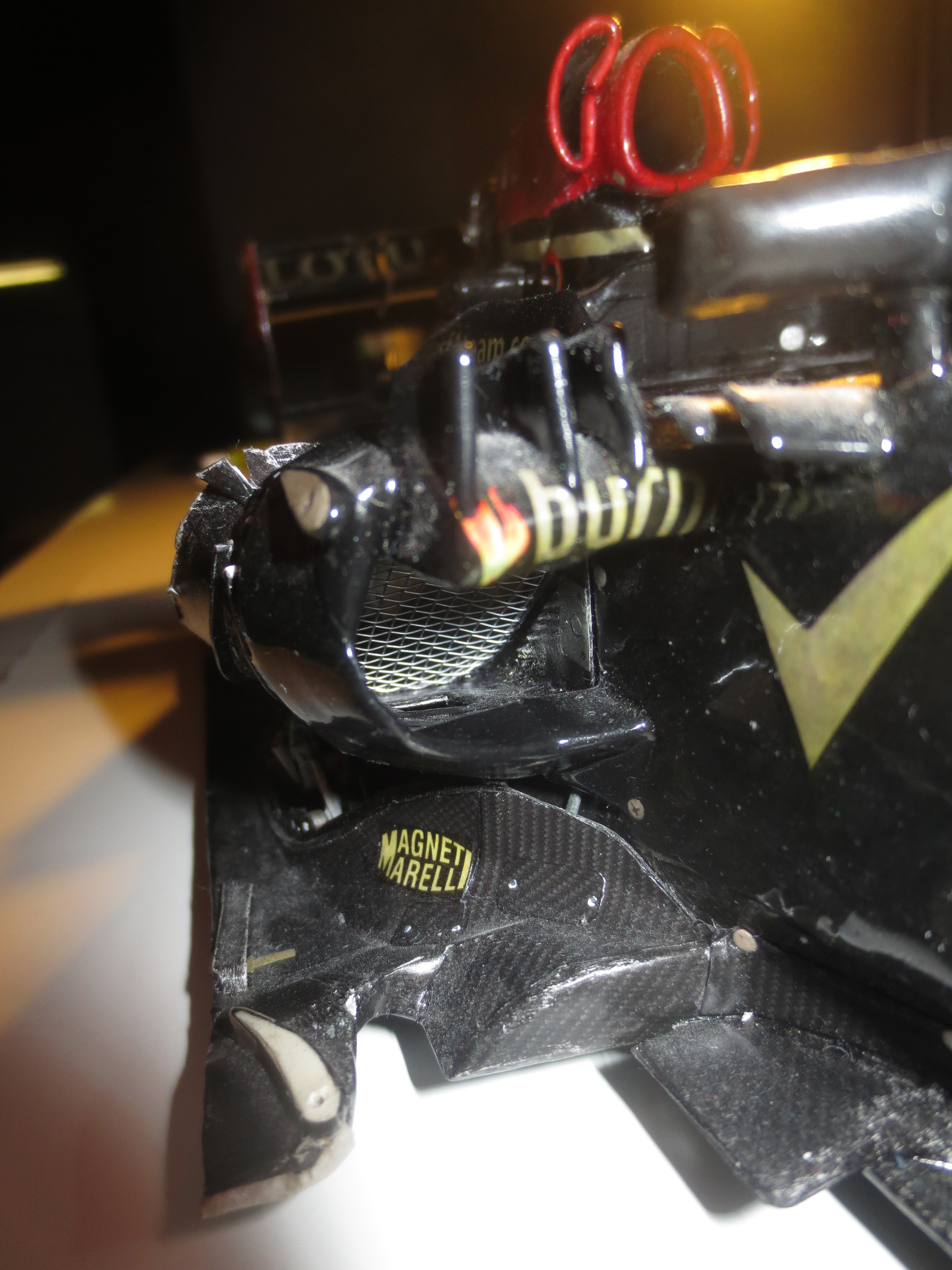
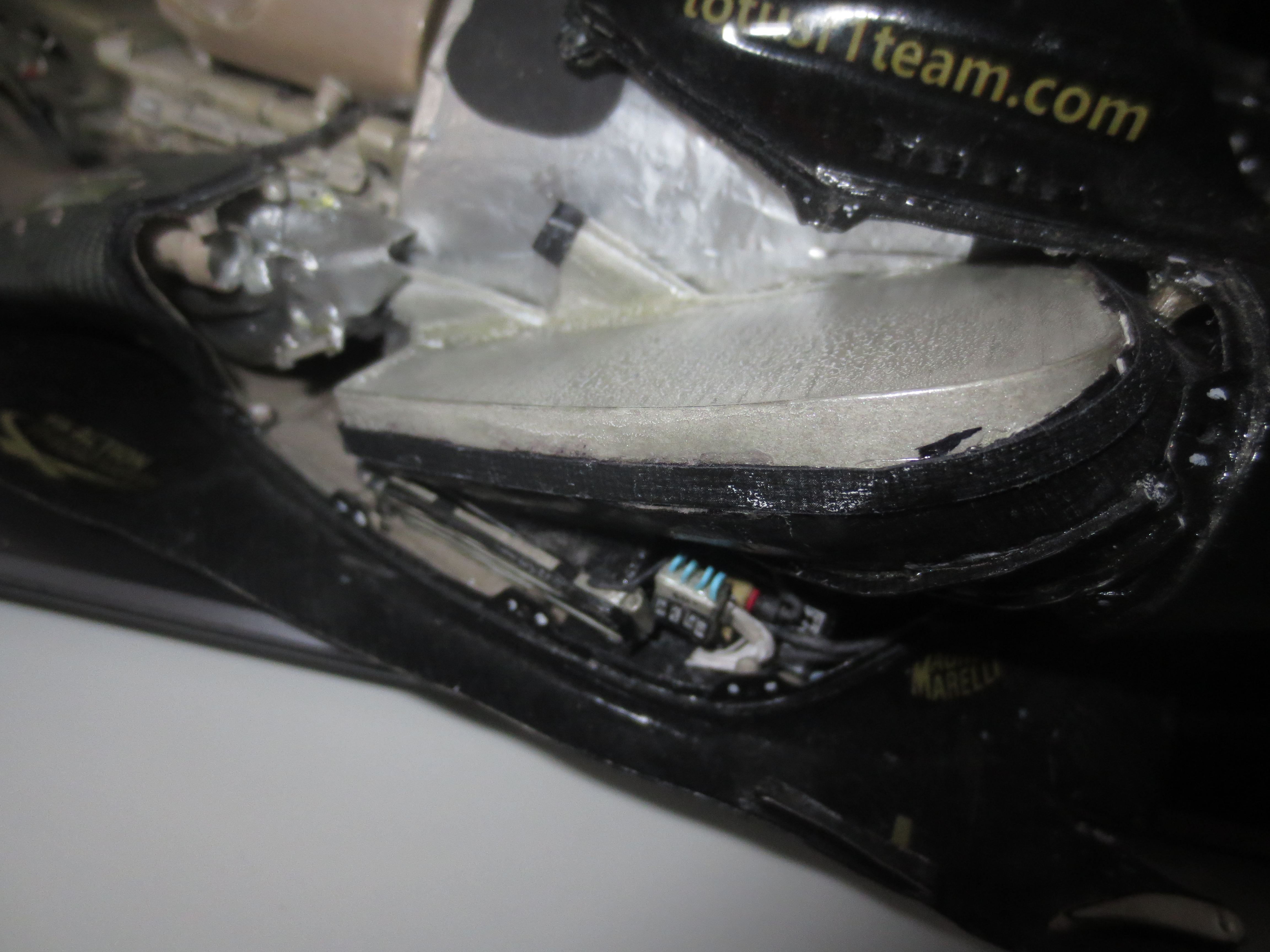
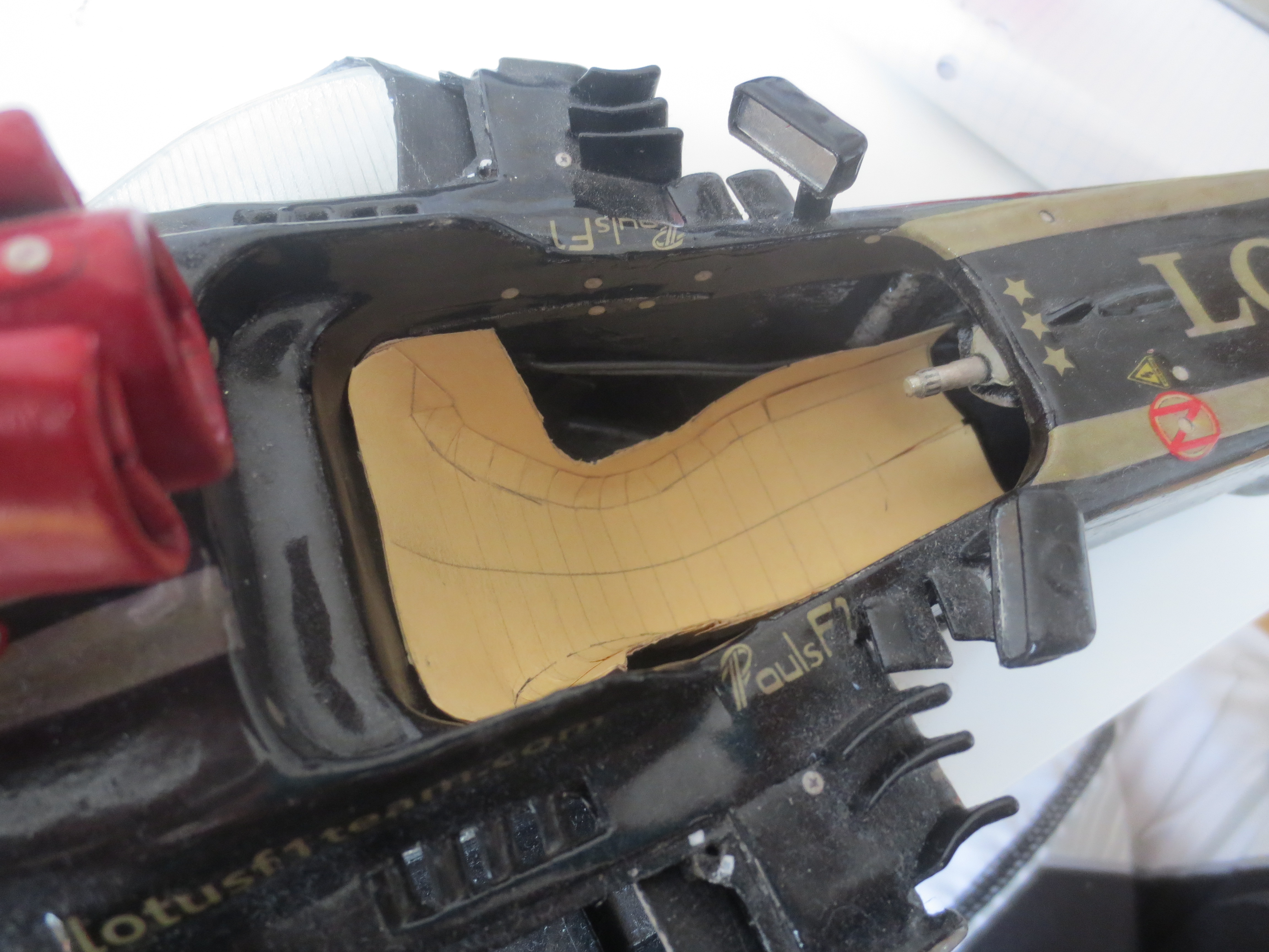
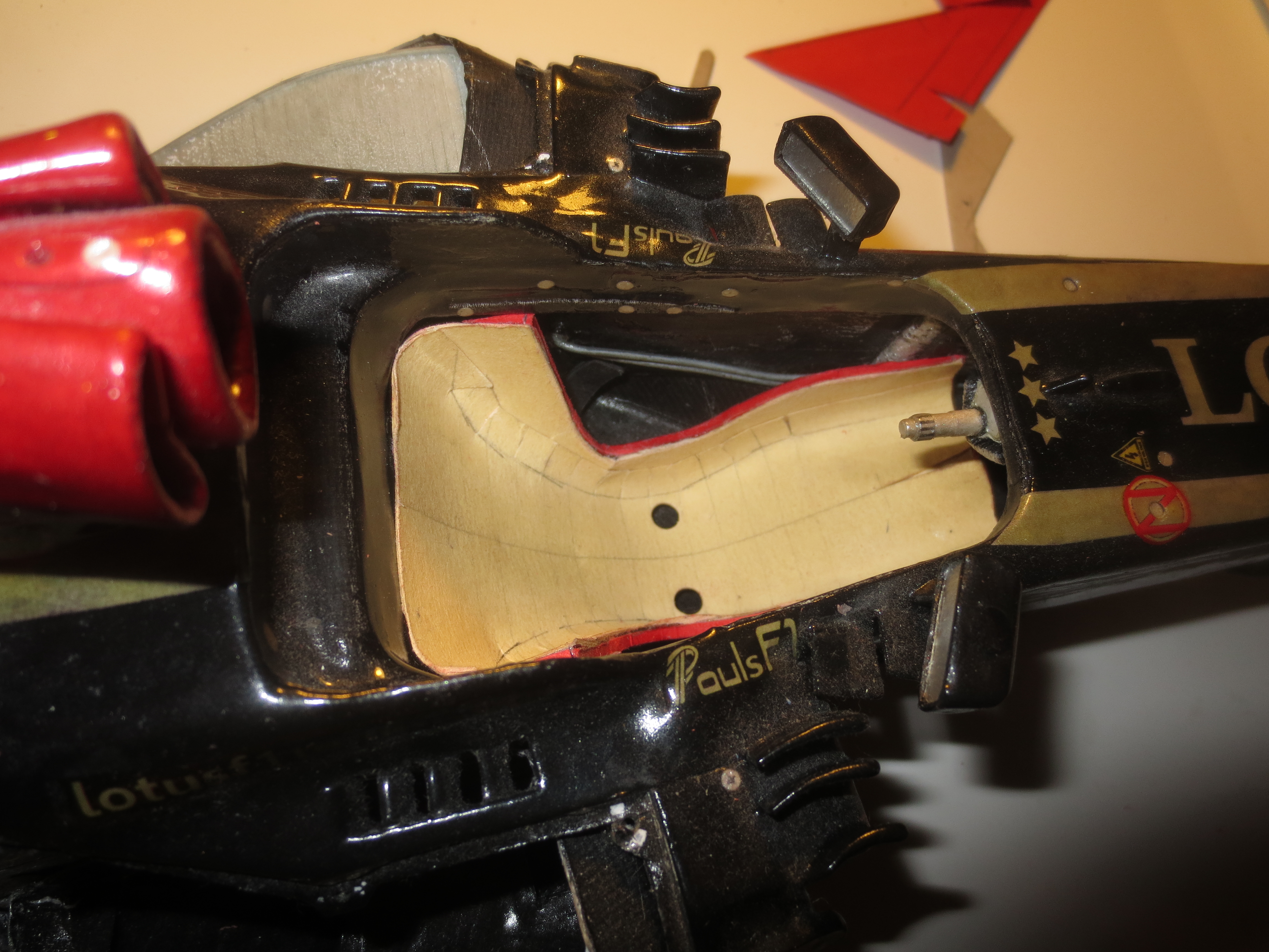
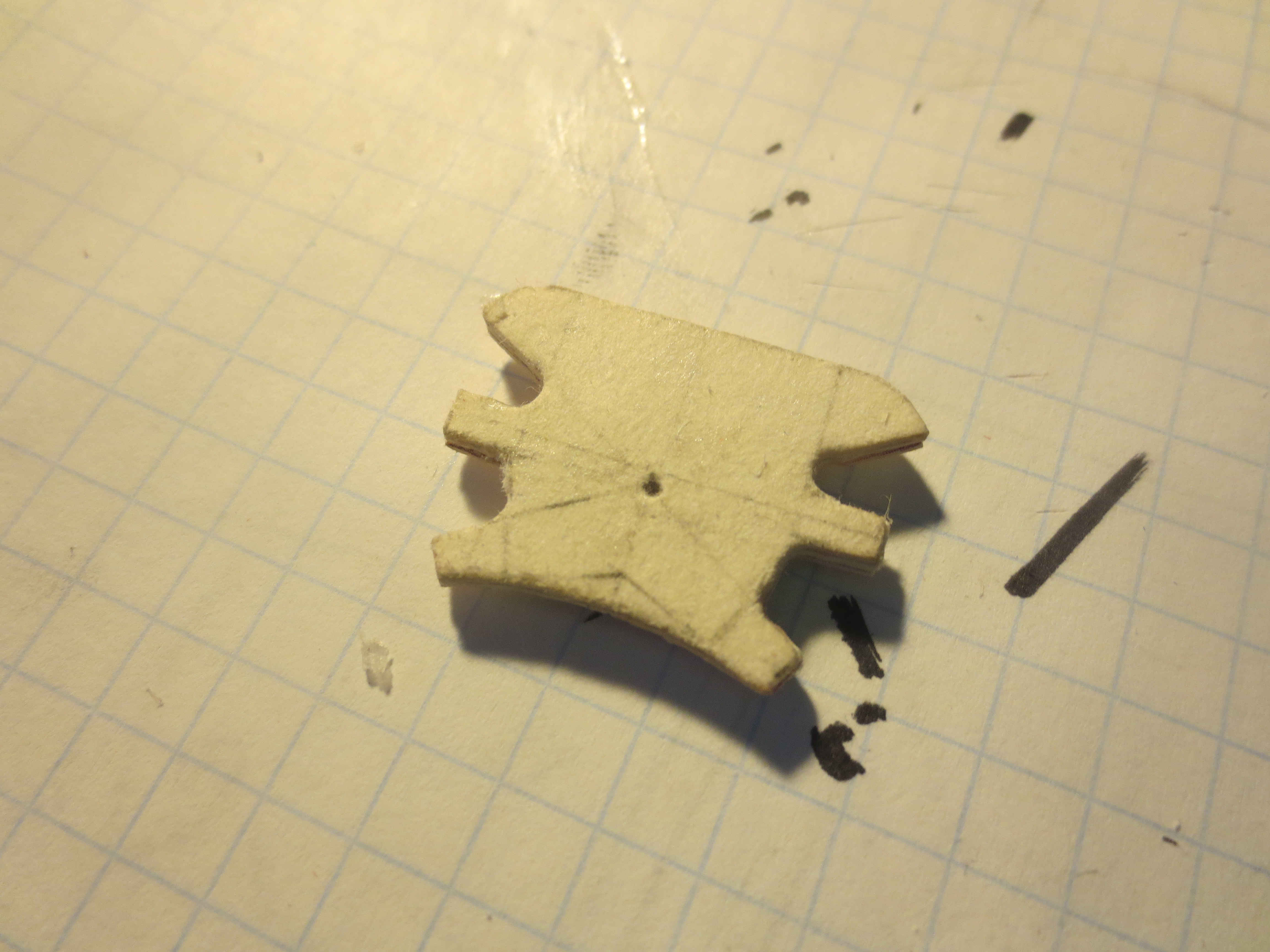
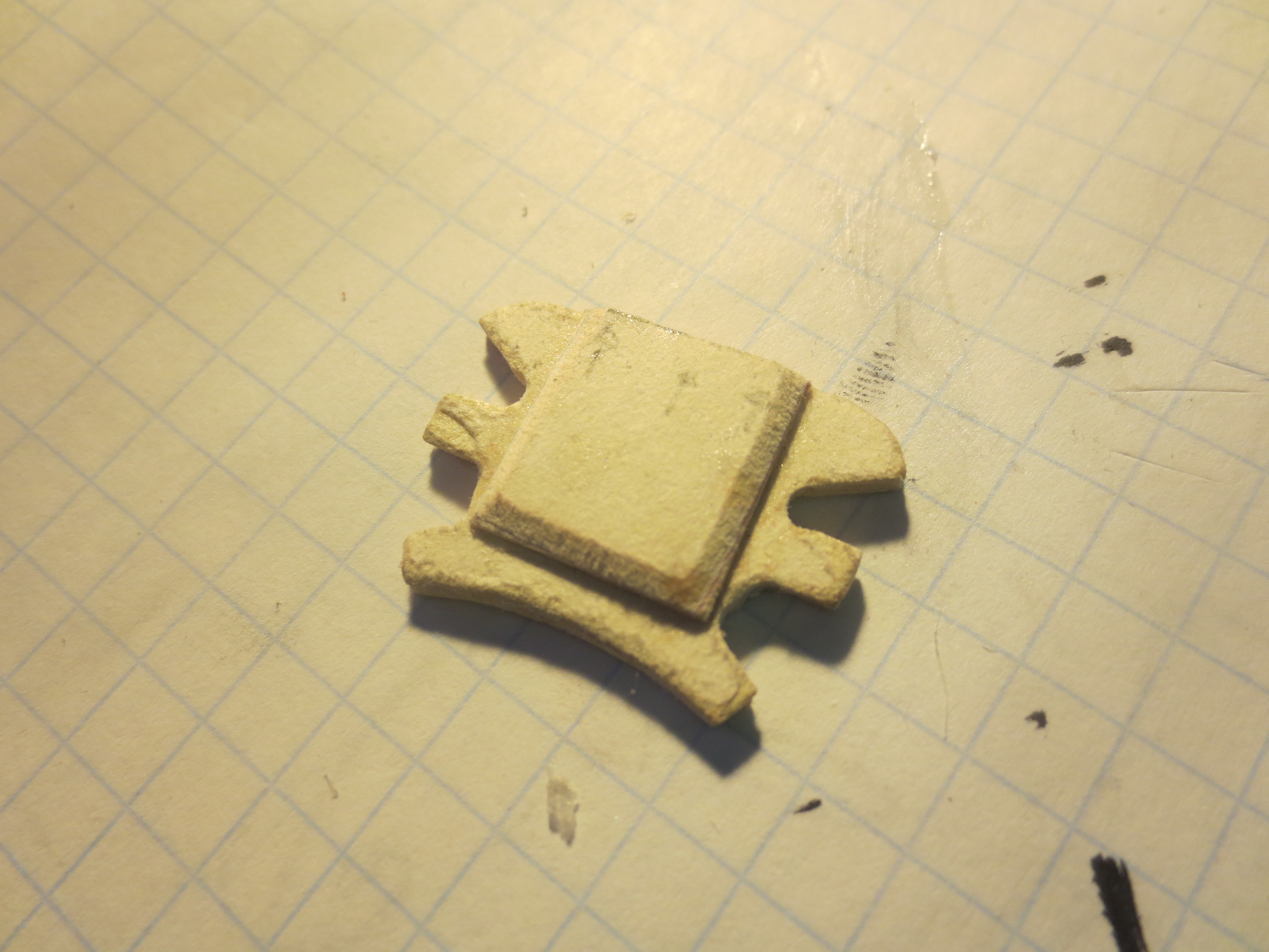
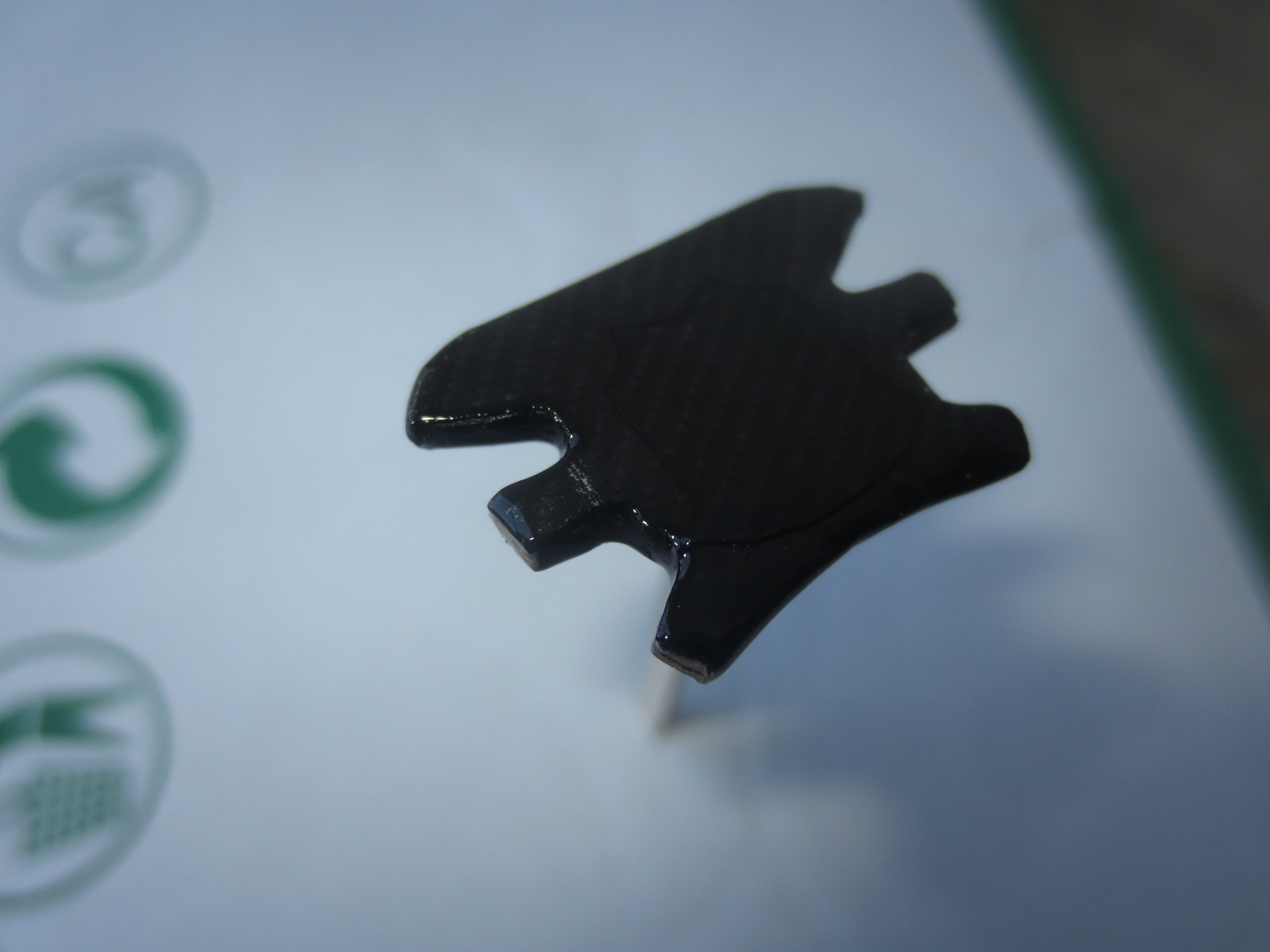
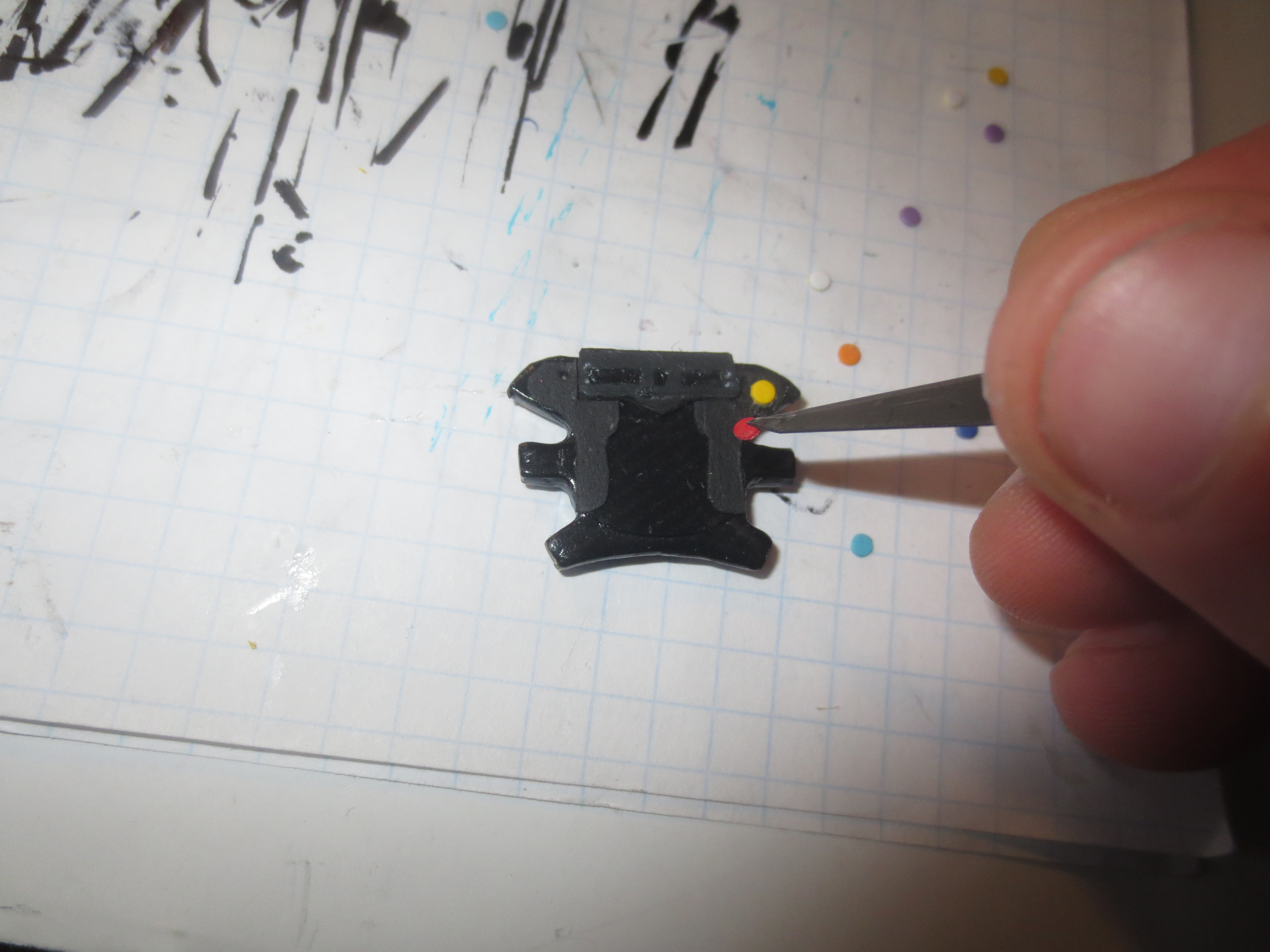
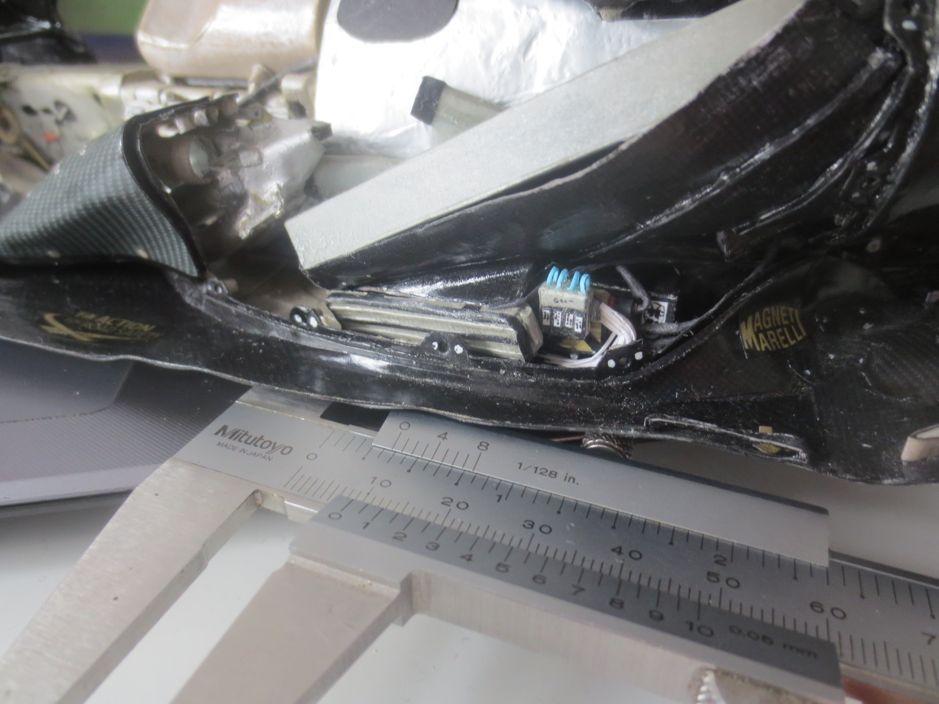
And finally, a premiere: For the very first time, I designed a working rear light. It was a bit of a challenge to find appropriate electronic components. The geometrical boundary conditions are 9.5mm x 11.5mm in cross section (inner dimensions of the rear crash structure). Finally, I found a 6V micro cell battery (for an LED, a minimum voltage of 3V is required) with 10mm in diameter and 16.3mm in length. A sliding switch with 20mm x 14mm x 8.5mm was too large. Even if I removed the unnecessary material, the switch is too large. So my electronics consists only from the battery with a cardboard pick up structure, two LEDs incorporated in the light housing and wiring. It is just enough space to get it fit into the rear crash structure.


Lotus E21 construction report part 26
Engine cover with PDRS, internal areo devices, fitting last barge boards and starting wheel design.
A lot of time passed by since my last post, mainly caused by moving into a new flat. However, I can report some new bits on the car.
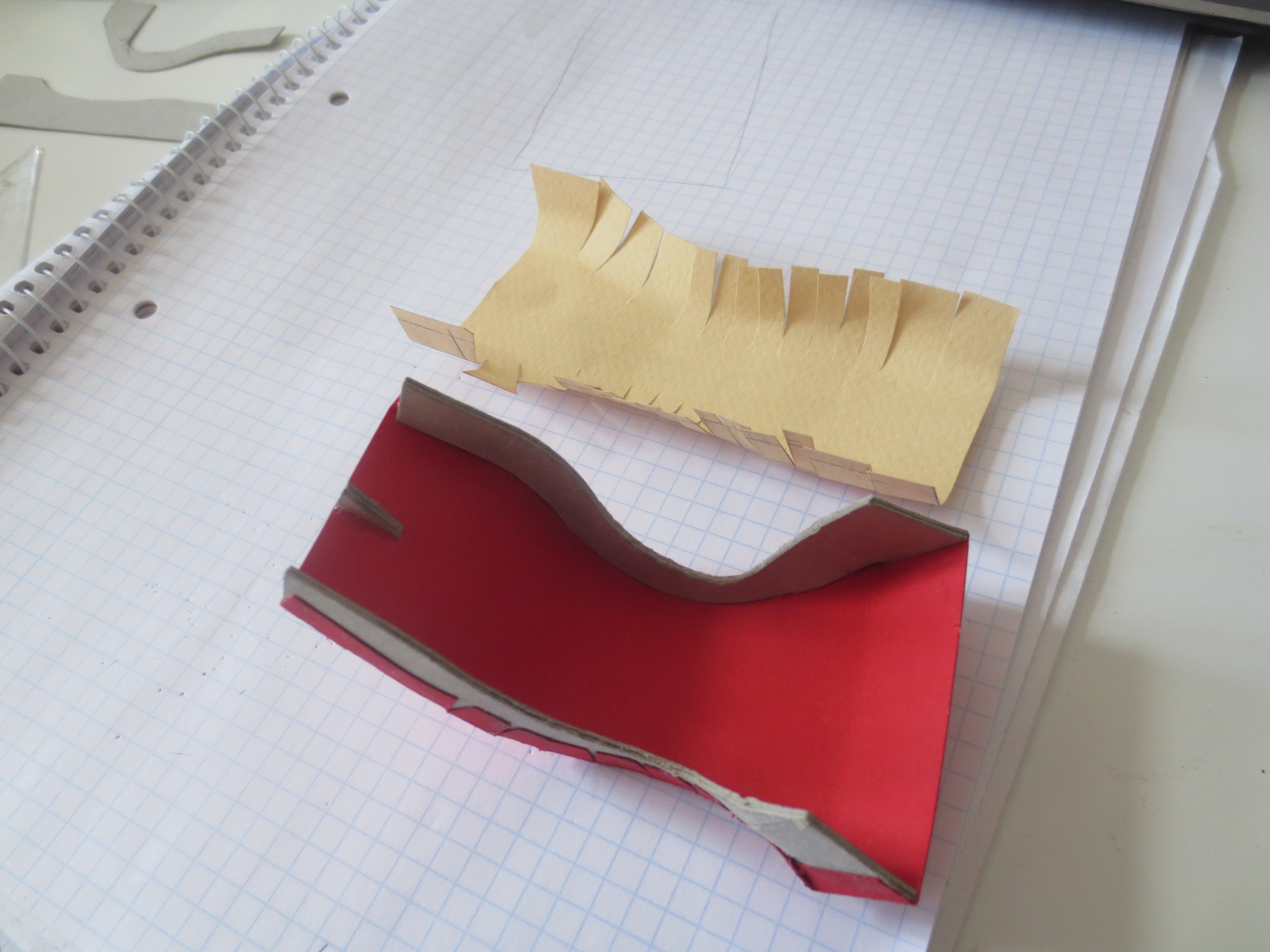
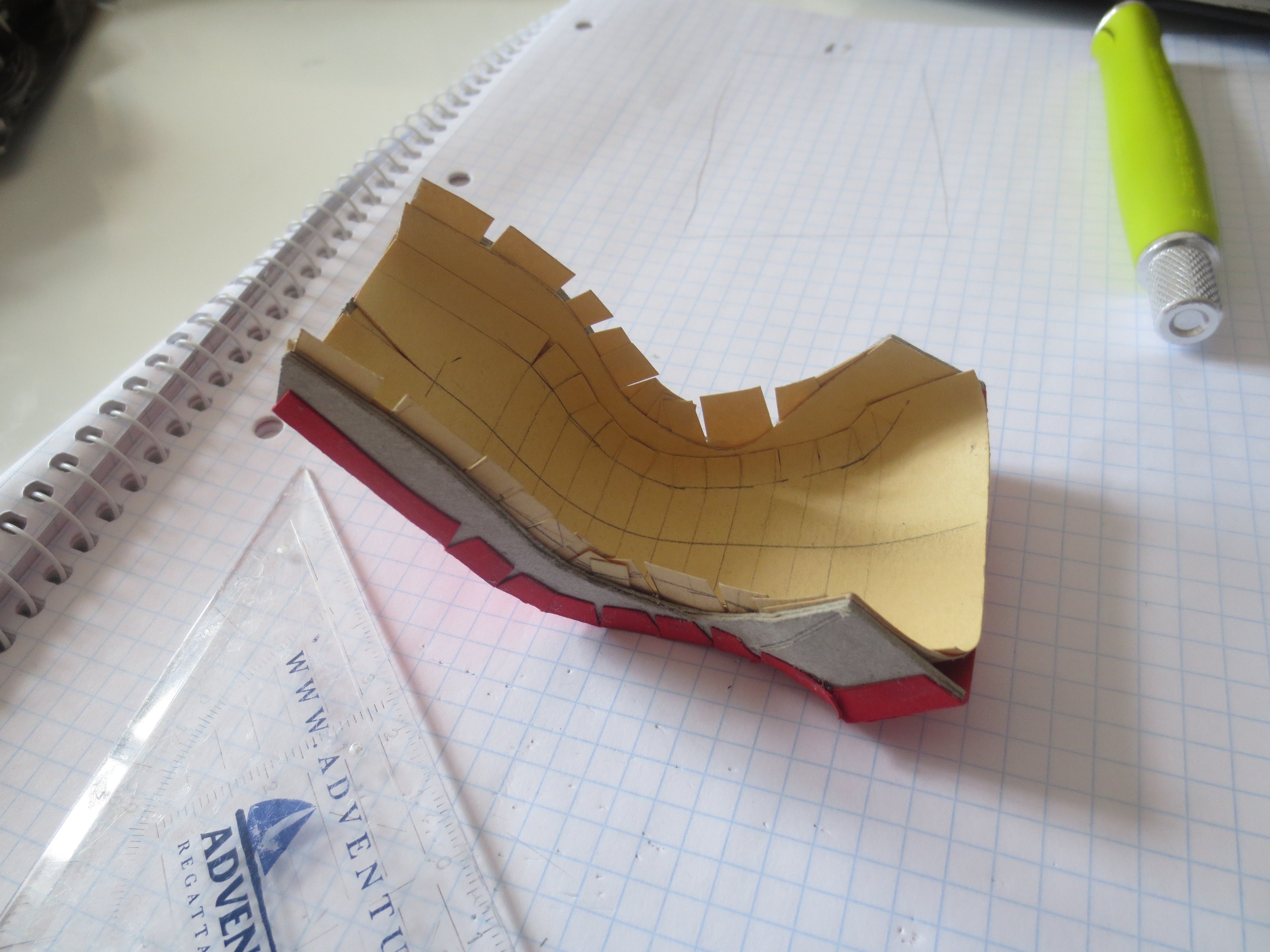
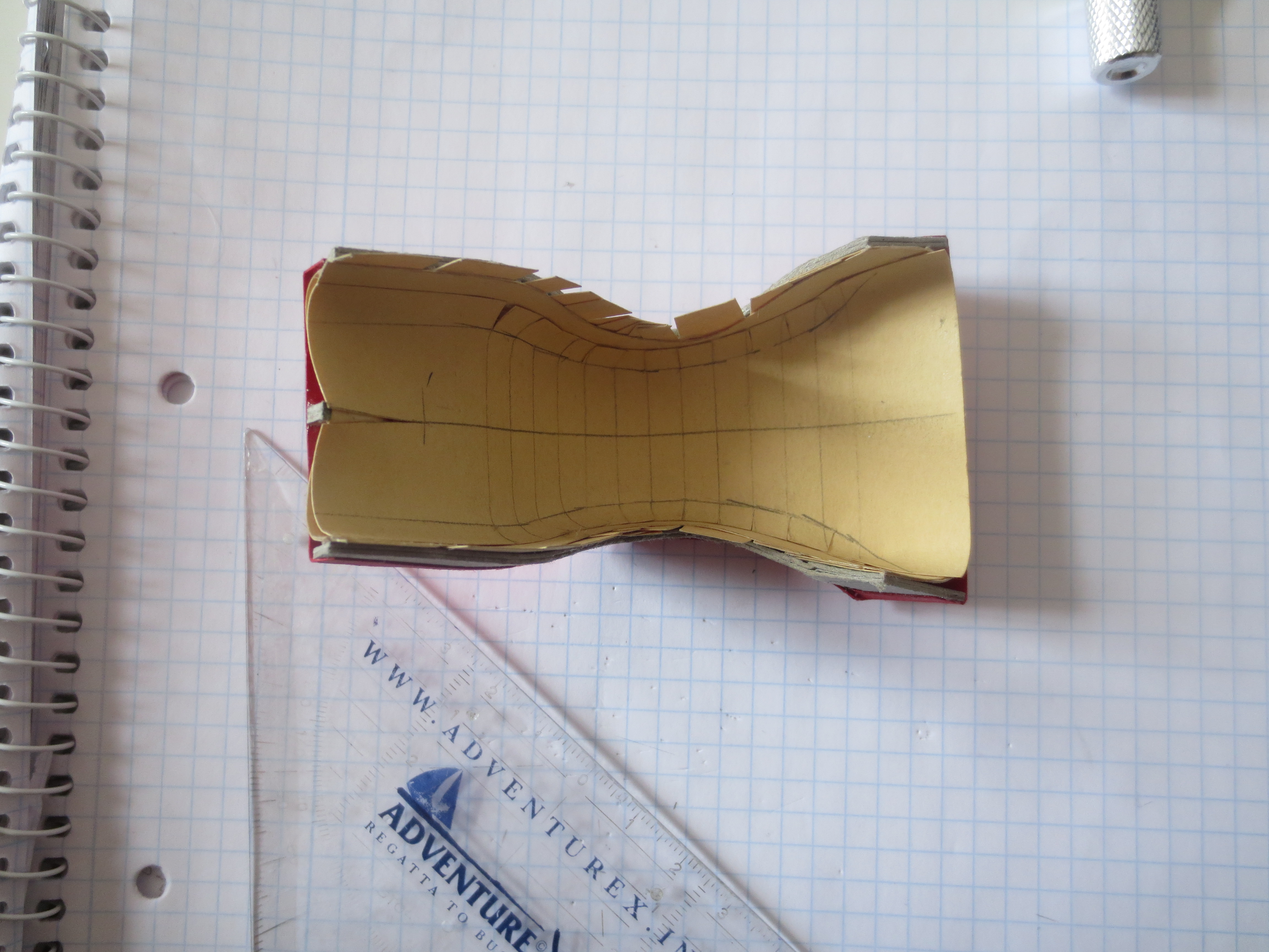
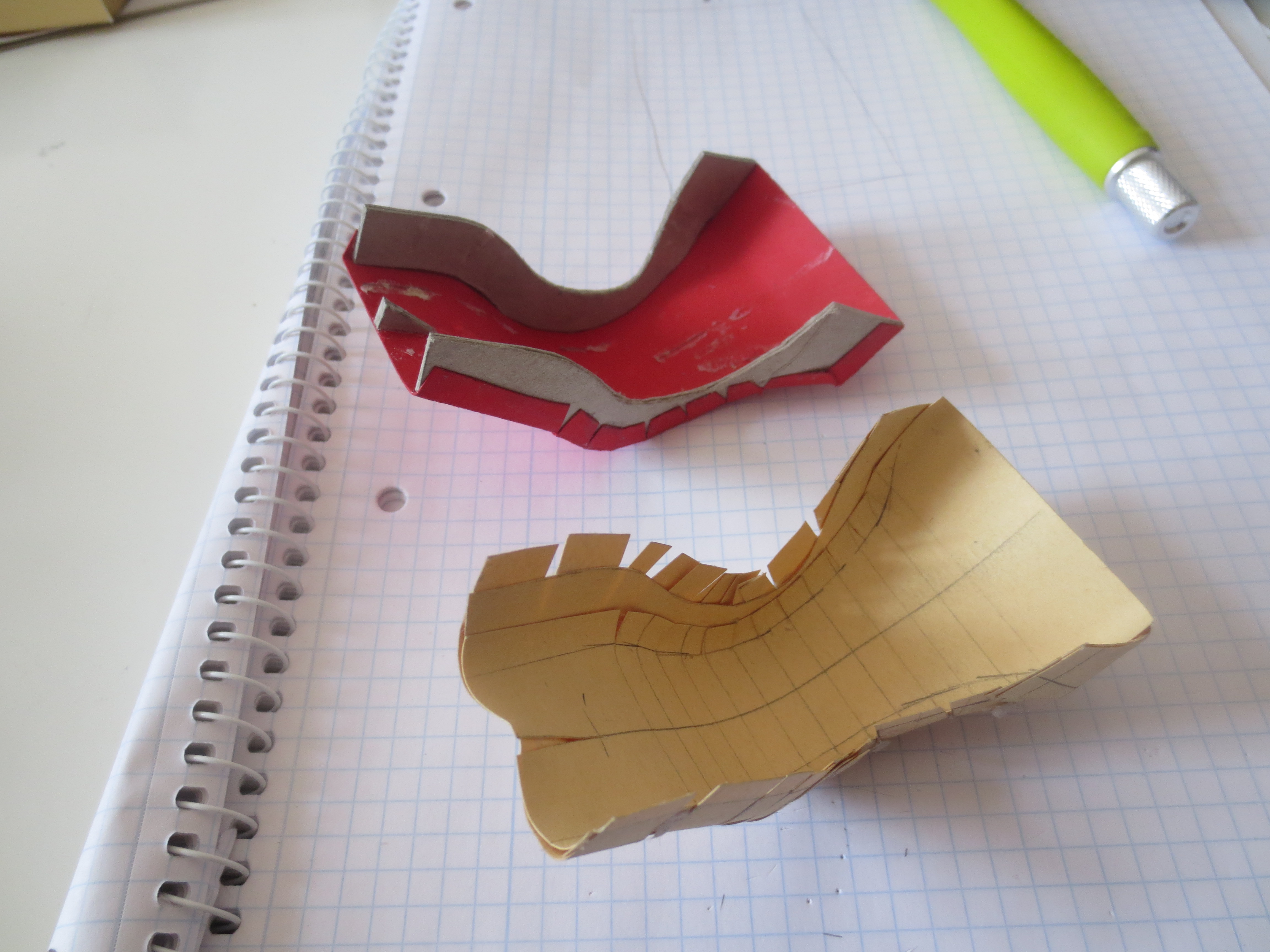
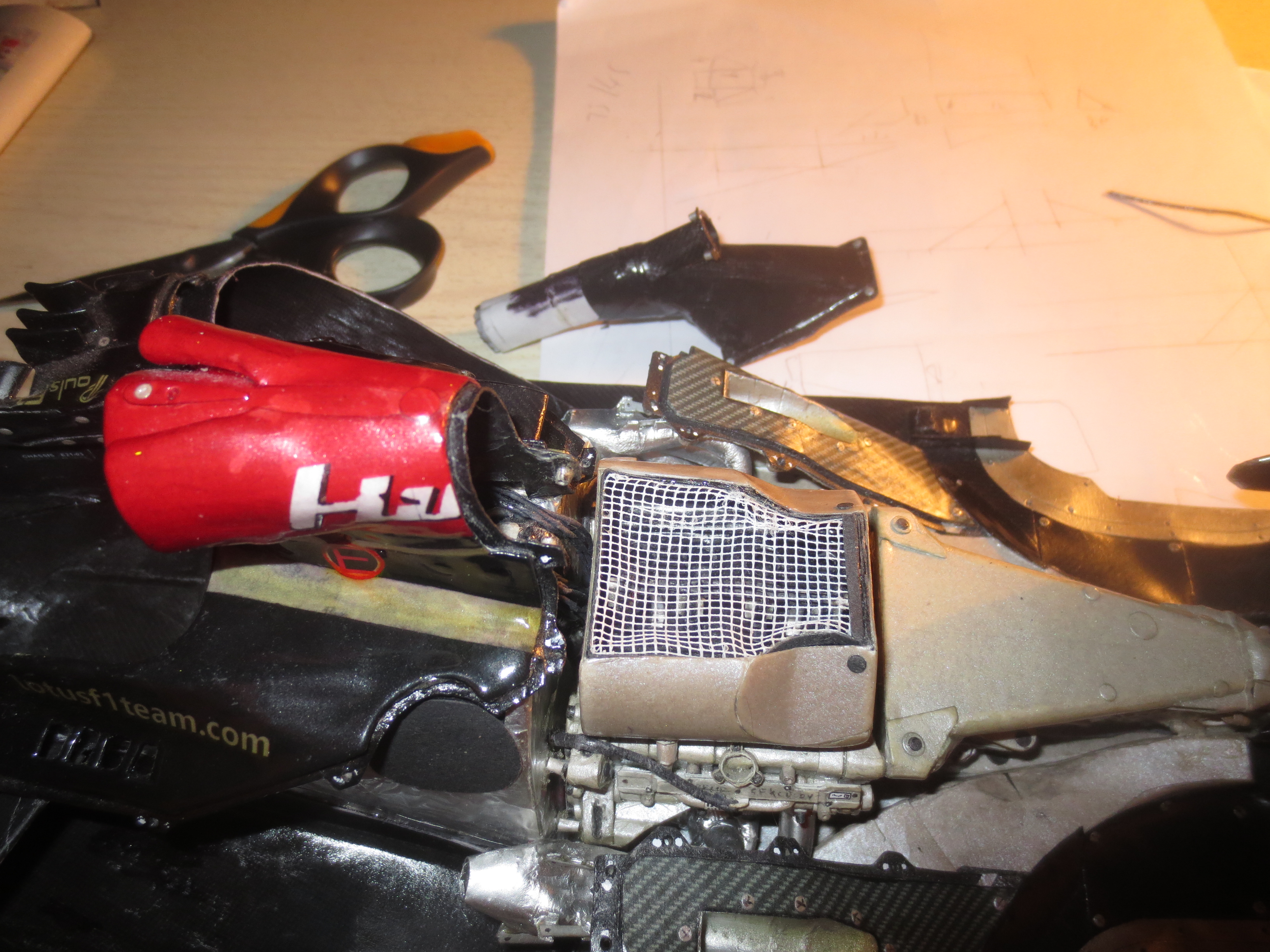
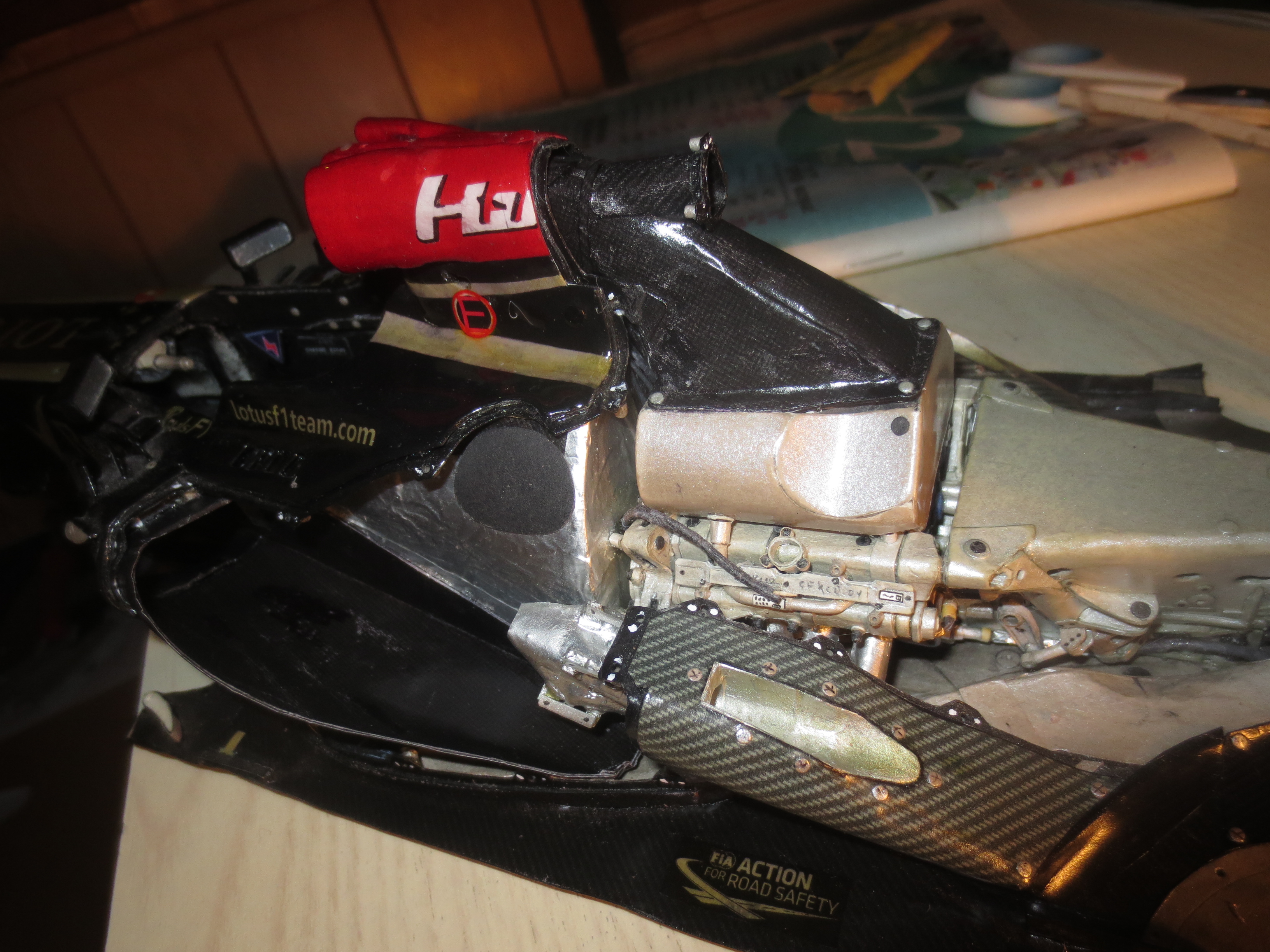
First to the engine cover. Maybe the most tricky part/assembly on the whole car. As mentioned in the previous post, I cannot produce the engine cover exactly to its original dimensions, but I have to adapt it to the bodywork that is already fitted to the car. This is a process, that usually takes a lot of time and several prototypes (up to twelve in case of a Renault R26 ten years ago) are made on my previous cars. On the Lotus I surprised myself in building only two protoype engine covers till I reached the ideal shape. The engine cover consists of five main elements (one cover each side pod/radiators, one over each side of the engine, central piece at the top/airbox) plus the PDRS duct.
PDRS means Passive Drag Reduction System and is actually a passive f-duct system. A few teams (for example Lotus and Mercedes) tried to get them work and actually tested them on track. As this system with its (passive) fluid switch is highly complex and no team was able to get it work properly (as far as I know and remember). Also Lotus aborted the project after FP2 at Belgium GP in 2013. However, due to their limited resources, they used one airbox with its PDRS inlets over the entire season and only closed them, when PDRS was not in use.
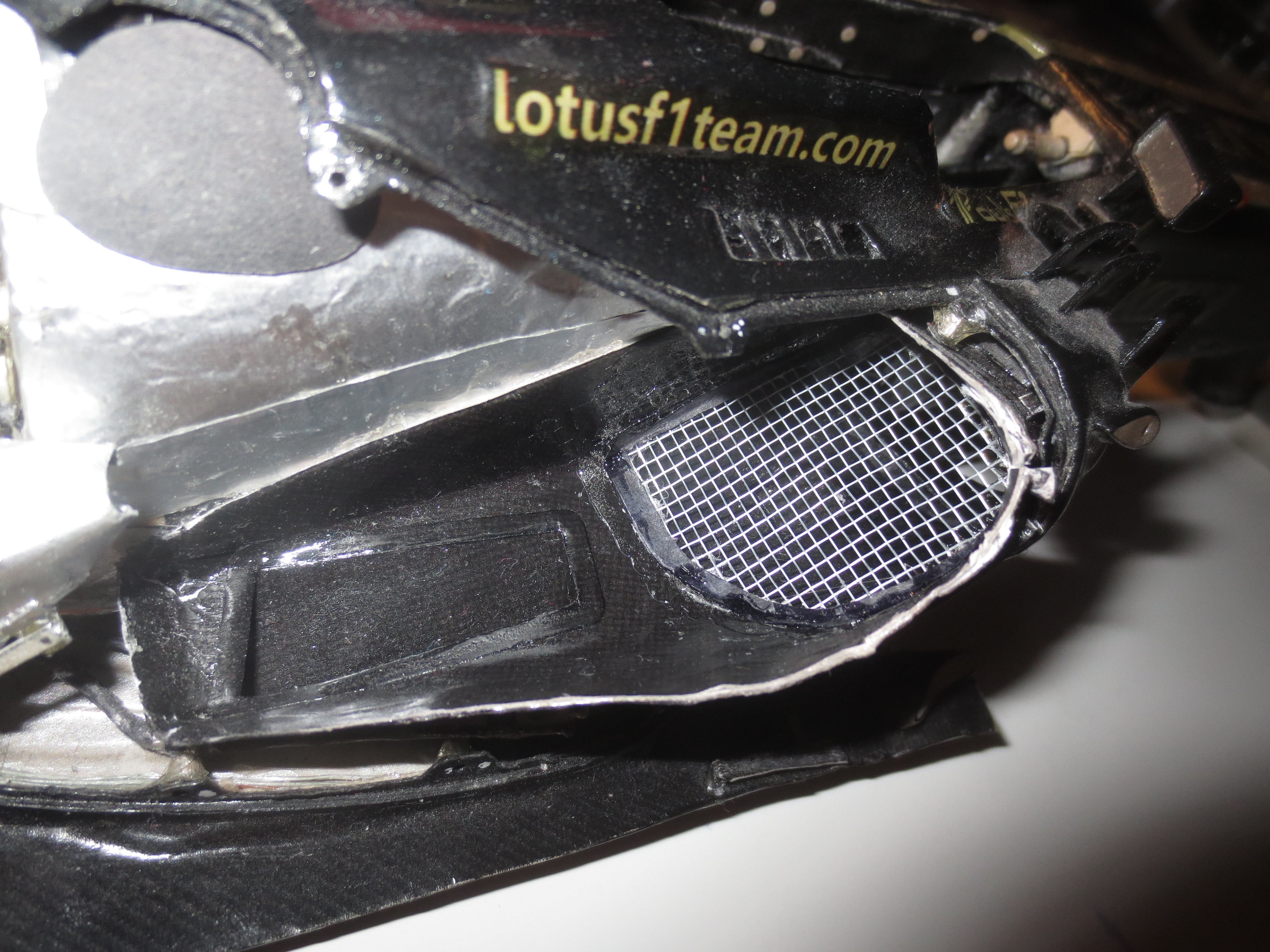
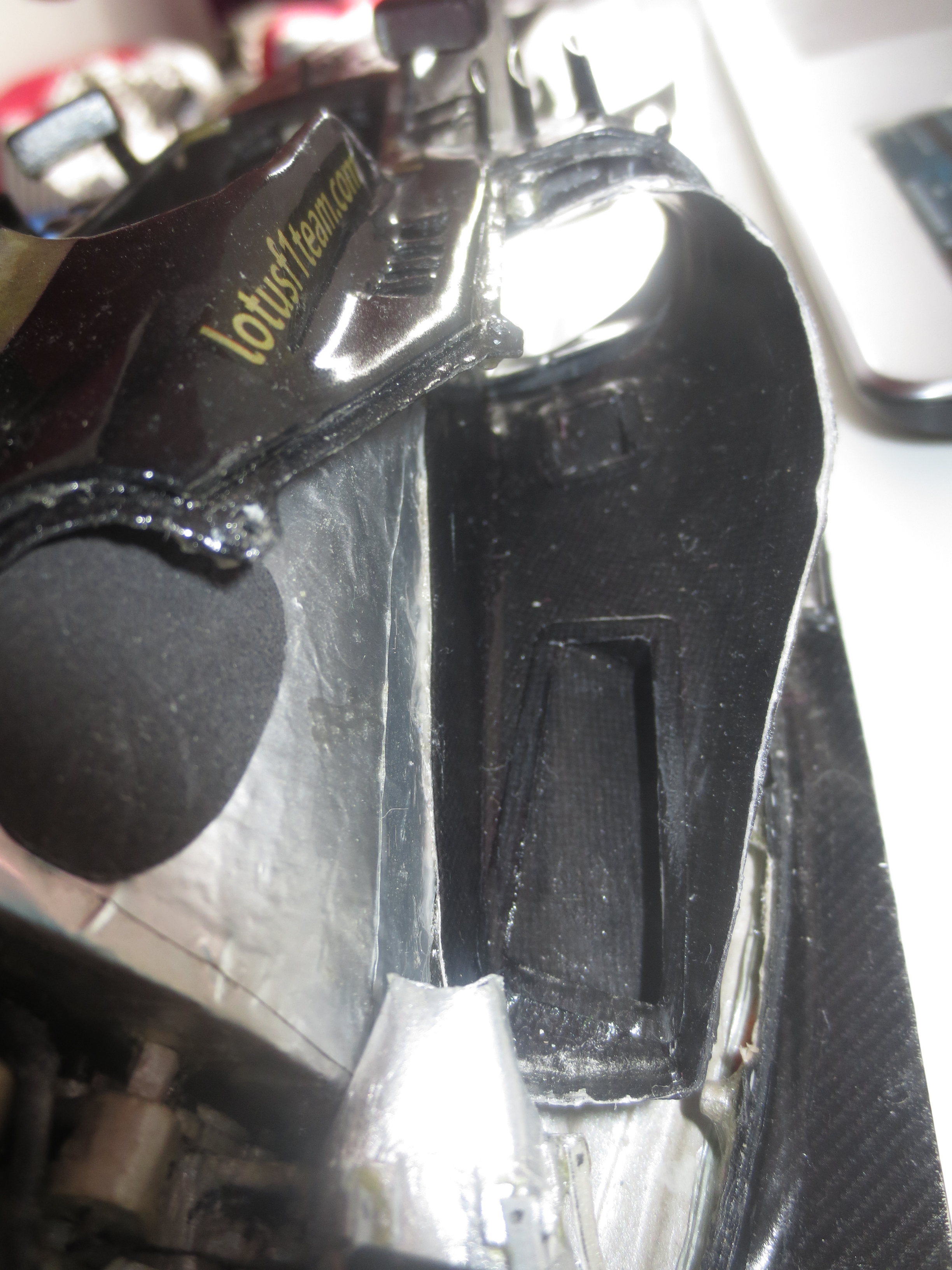
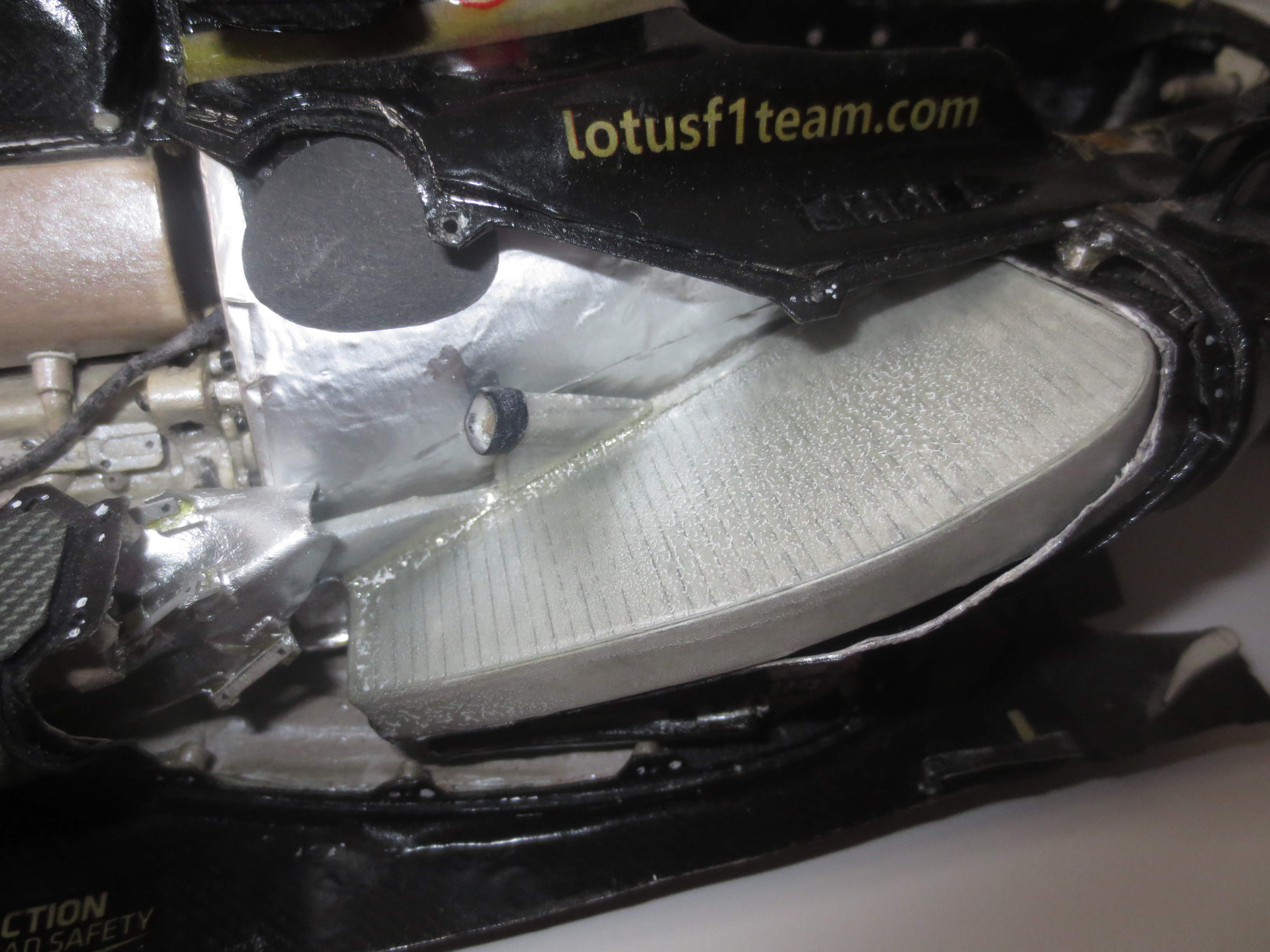
Secondly, the shape of the internal areo covers are finished and only needs to be covered with carbon texture. The intention of the internal areo devices is to reduce the drag of the internal airflow. These internal areo covers appeared first in the 2009/2010 season. They mainly cover the engine and secure a relatively clean surface to minimise the drag for the airflow which exits the radiators.
I also started to fit the last barge boards, which I already produced a few month ago, but did not fit them in order to prevent damage in the course of working on the car. Now, the car is almost finished, and I don’t need to work at the car directly any more – so no more danger of damaging them.
The last major project are the wheels. Unfortunately I was not able to find a proper gold paper (the Lotus rims were painted in gold each year). So I have to produce the structure of the rims from white paper and cover it with thin gold paper. Not the perfect way…
Remaining to-do’s are:
- Finishing rain light
- Wheel nuts
- Finishing wheels
- Cover internal aero with carbon structure
- Fitting pre-manufactured items (wind screen, top camera, antenna, pitot-tube)
A few pictures from the engine cover production:


And a few of the finished engine cover.


Some more of the internal aero devices, barge board and starting point of the wheel manufacturing.


Lotus E21 construction report part 25
Brake ducts, wheel hubs, cockpit padding, start designing engine cover and internal aero devices.
The brake ducts/drums are pretty complex shapes, but were fun to build. They are, even if they are 2013s, actually not less complicated than 2017 brake ducts. The packaging of the whole brake ventilation stuff is impressively thight (as almost everything is on this car – but not that extreme as the 2014 upwards car generation). The rear drums feature a row of little wings to generate downforce directly at the wheel. The front ducts only feature a few vanes.
The wheel hubs are relatively simple shapes, but each consisting of 16 parts. Front and rears are almost identical.
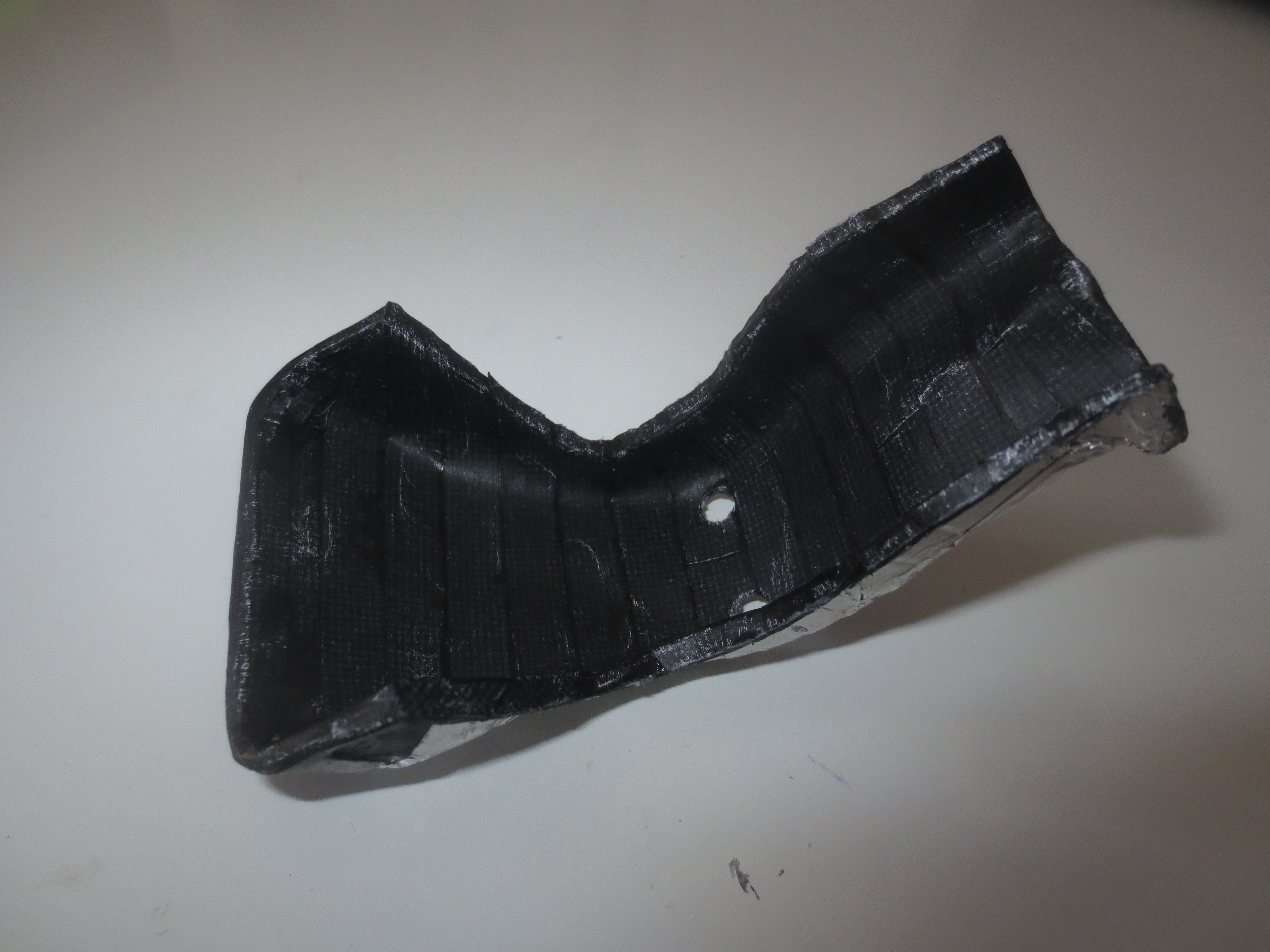
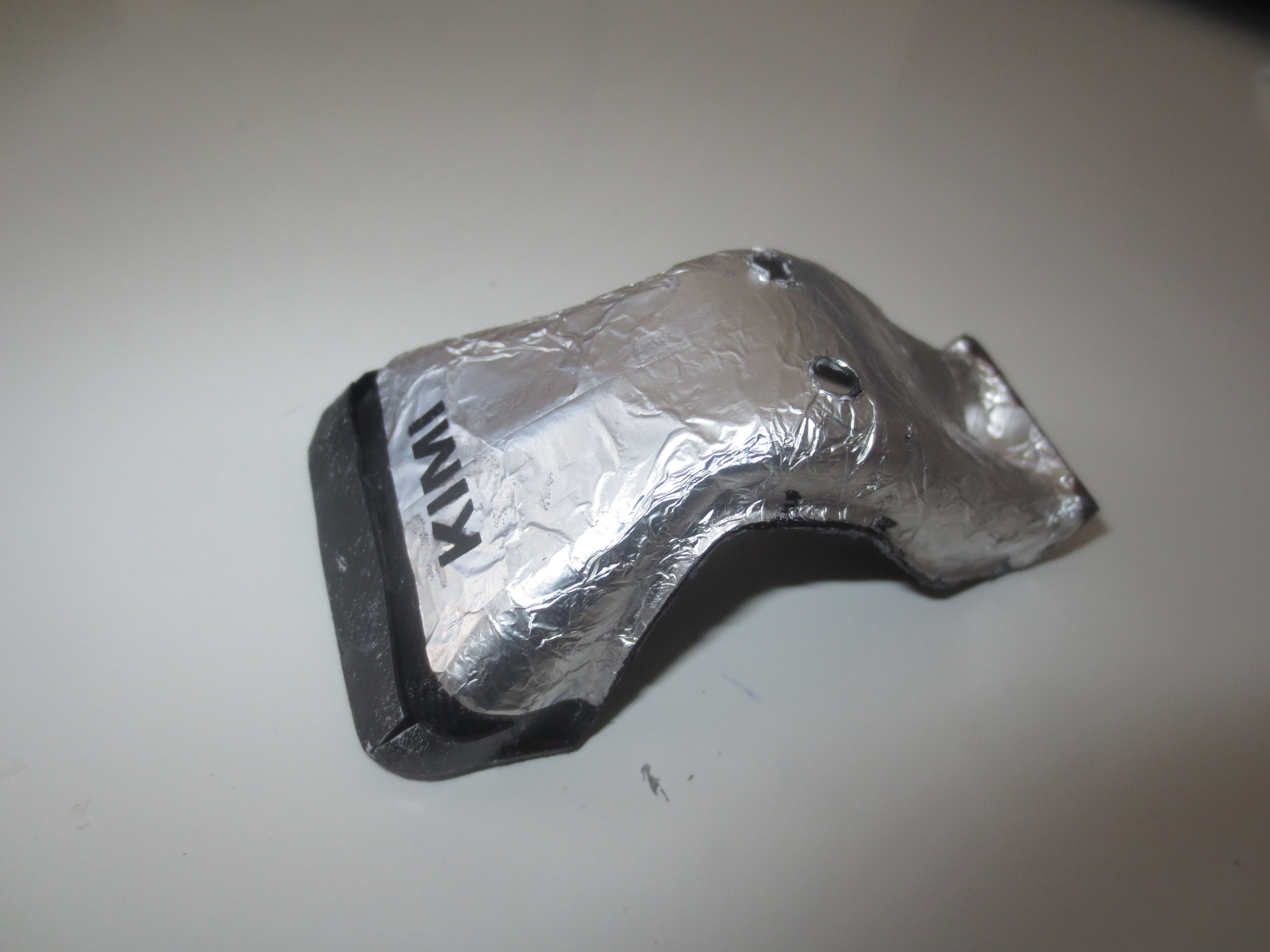
One of the most complicated things to design and manufacture is the cockpit padding. In real-life, it is filled with a foam. My one includes a structure inside and is covered by black paper. The difficulty here is, that the cockpit opening is not to 100 per cent exact (means also not 100 per cent symmetric). So I had to design the padding not to the exact original measurements but to the model’s shape – finally it is slightly asymmetric, but it fits pretty well.
Probably the most complex part on the entire car is the engine cover. Same as the cockpit padding, its shape has to be designed to the already existing bodywork on the model. Surprisingly the first design was already pretty good. Just two prototypes had to be designed till the right shape was found.
Remaining to-do’s:
- Finishing rain light
- Wheel nuts
- Wheels
- PDRS
- Engine cover
- Internal aero
I don’t like to place another completely wrong estimated date of completion – like I’ve done in the previous post. 😂


Lotus E21 construction report part 24
Brakes, safety belts, cockpit electronics, starting cockpit padding, brake ducts and rain light.
And again two and a half moth flew by since the last post. This time again some bits are fitted to the car and the to-do list gets shorter and shorter. The completion of the car comes closer and closer. An expected finish could be at earliest by the end of April.
Remaining to-do’s:
- Finishing cockpit padding
- Finshing brake ducts
- Finishing rain light
- Finishing wheel hubs
- Wheel nuts
- Wheels
- PDRS
- Engine cover
- Internal aero
The first five bits on the list are a work of maybe two weeks. The car is looking more and more attractive from day to day. But to increase the suspens till the “roll” out (maybe better move out), there won’t be any picture of the ful car any more. Just on details. 🙂

Brakes with first parts of the brake ducts. There were some thougts to make the brake ducts/covers demountable (and therefore detail out the whole brake duct stuff). But that may cause the wheels groggy when mounted…


Finally all cockpit electronics done. I am not sure at all, if this looks like the real car. But I incorporated all electronic stuff a F1 car has into the car. So there wasn’t actually much left for the cockpit. So it looks maybe a bit empty. Anyhow, it does look not too bad.


Cockpit padding in its current stage.

Original drawing of the rain light. Thanks a lot to McLaren Electronic Systems to provide this data for free! Original link is below.
Lotus E21 construction report part 23
Cockpit electronics, suspension stuff, exhaust system, brake discs, internal aero and more.
This post sumarizes the work I’ve done over the past two month. A lot of small stuff like fuel fillers or electronic boxes, but also massive projects like front-and rear suspension and exhaust system.
The completion of the car is optimistically aimed to early spring, maybe March. Unfortunately it is too cold now, to do the paint jobs on the balcony. So the flat is a bit smelly from time to time. 😀
The to-do-list is pretty short now:
- Belts
- Cockpit padding
- Brake calipers and cooling ducts
- Wheels, wheel hubs, wheel nuts
- PDRS
- Internal aero
- Engine cover
- Rear light
Next to come are the brakes.

Exhaust system is done. The packaging is really thight and it will get interessting to wrap the engine cover around it.

Gearbox and clutch control unit on top of the gearbox housing. BTW. Lotus/Renault is one of the very few teams, which is still not using a carbon gearcase.

Cockpit internals are also done.

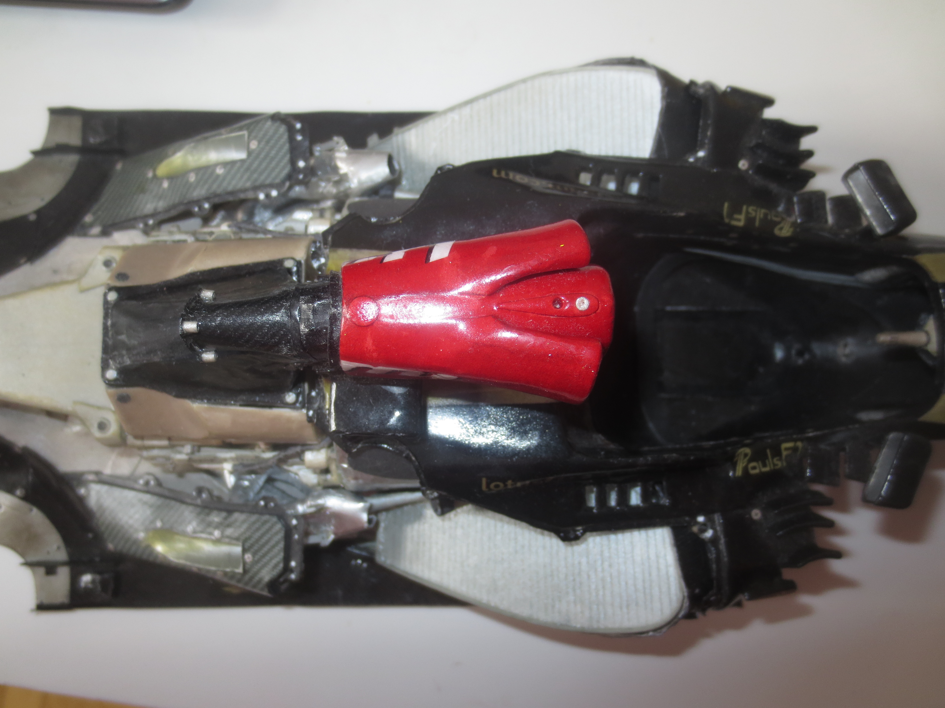
Fuel filler – top (red) one is the fuel valve, the bottom (red) one the venting.

Internal aero surface – this secures a clear and low drag tunnel for the cooling air.

Rear suspension

Front suspension – wishbone structure

Front suspension

Brake discs – each consisting from 19 parts
Lotus E21 construction report part 22
Brake fluid reservoirs, exhaust pipes, fire extinguisher, radiator pipes, beer and more…
Nice progress over the last days. There’s not a lot missing any more. Main sites are front suspension, brakes, brake ducts, wheels and engine cover.
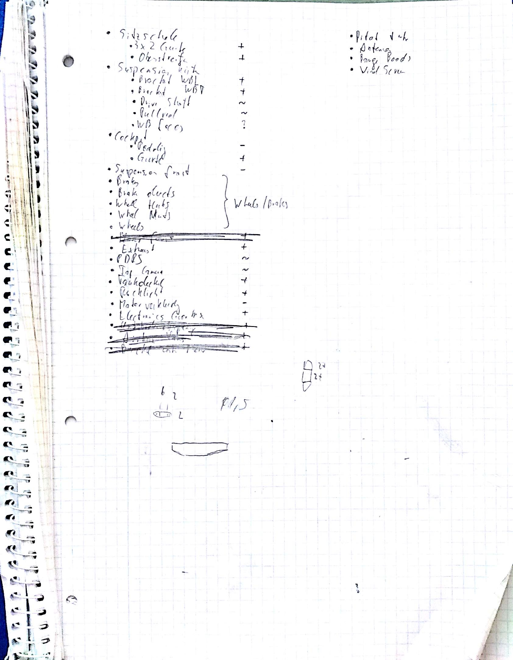
When I come to the end of a car build, I usually create a to do list with all the stuff on which is left. On this list I rate all elements with
+ which means, it’s an easy, quick and nice, simple to build element
~ which means, it’s a pretty simple element, but takes it’s time and is not that nice to manufacture
– which means, it takes a lot of time to build the element
Front suspension, cockpit padding and engine cover are the last three minus elements (maybe also the rims).
The components and assemblies, I produced during the last few days are stuff like exhaust end pipes (with their helmholtz resonater – more on that in picture caption below), fire extinguisher, brake bias lever, dashboard, roll sensor, brake fluid reservoirs, pitot tube and some electronic stuff at the front end of the chassis.
Beside all this, I created a rim instruction. So the rim design is already done.
Unfortunately I lost the drive shafts during the summer… 😦 So light delay at the rear suspension build.
At the moment, the car is at about 4000 parts.
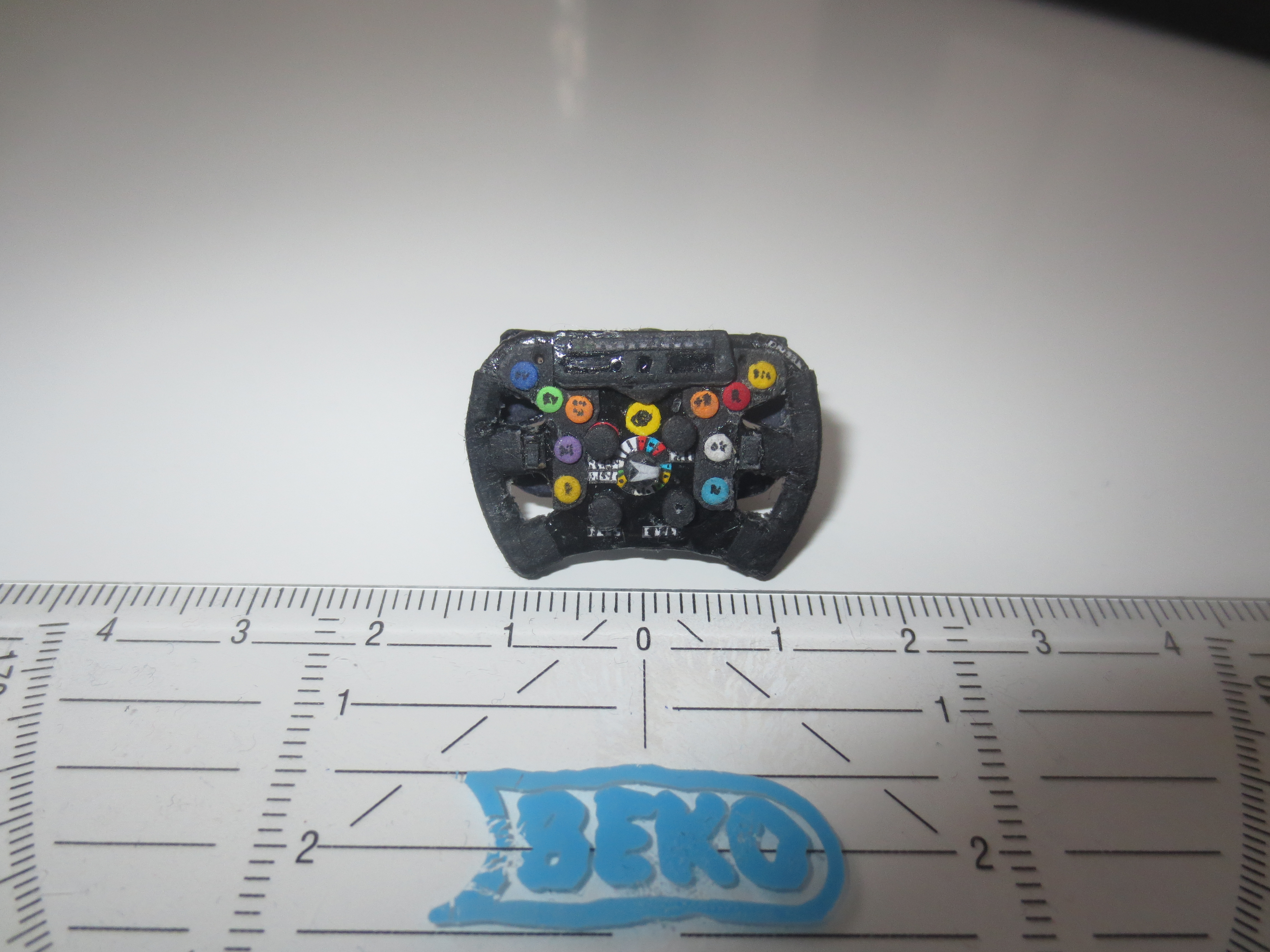
Front view of the steering wheel – it consists of 107 single parts and has a diameter of 27mm. For comparison, the RB7’s wheel has 73 parts and the R18TDI’s wheel (much bigger) has 109 parts.
Back view of the steering wheel with clutch and gear shift paddles. At the best sake, I can’t remember any more, what the top lever is. It seems, I got a little rusty… With the ruler beside, you can actually imagine the size of all these tiny elements.
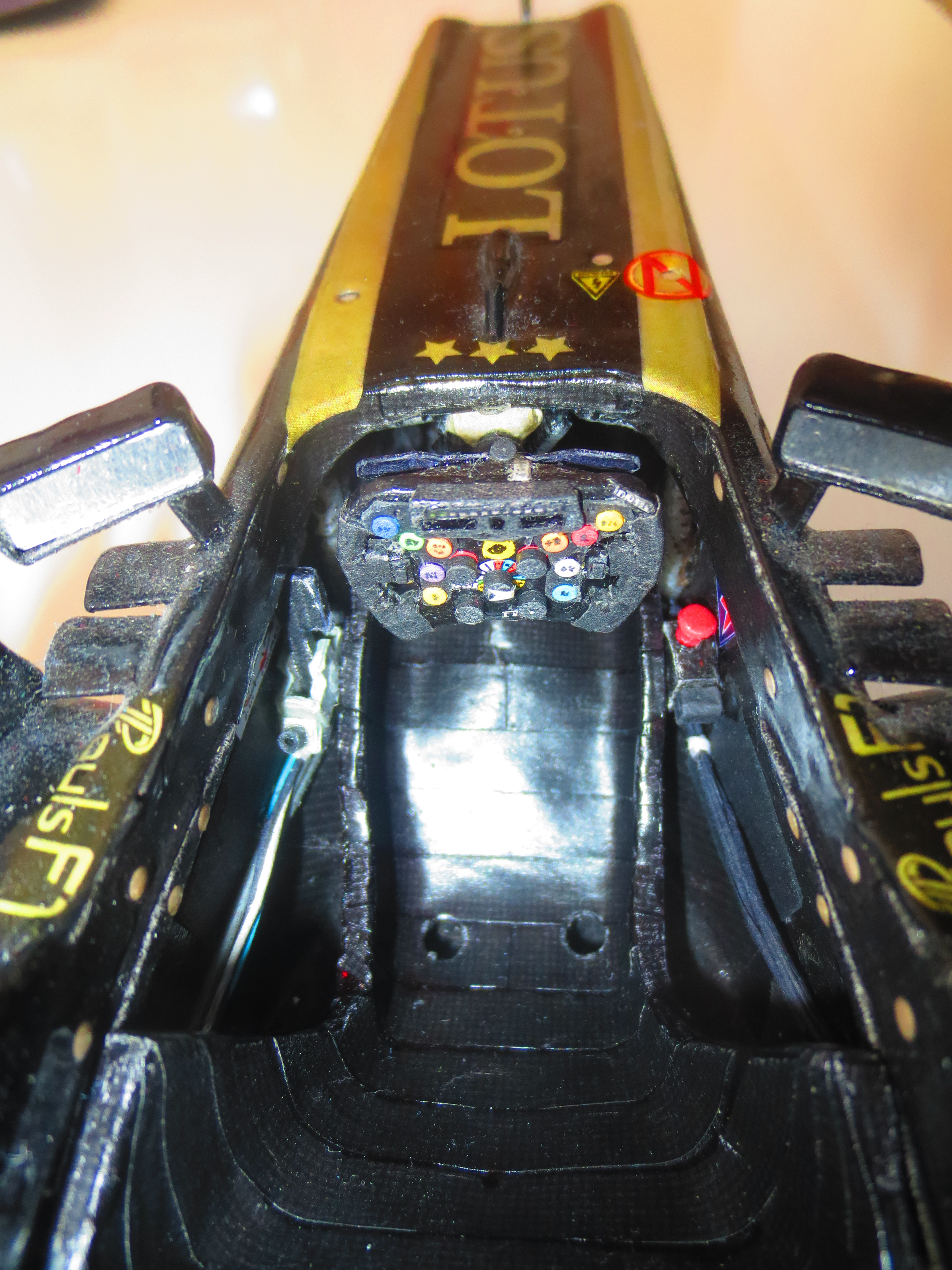
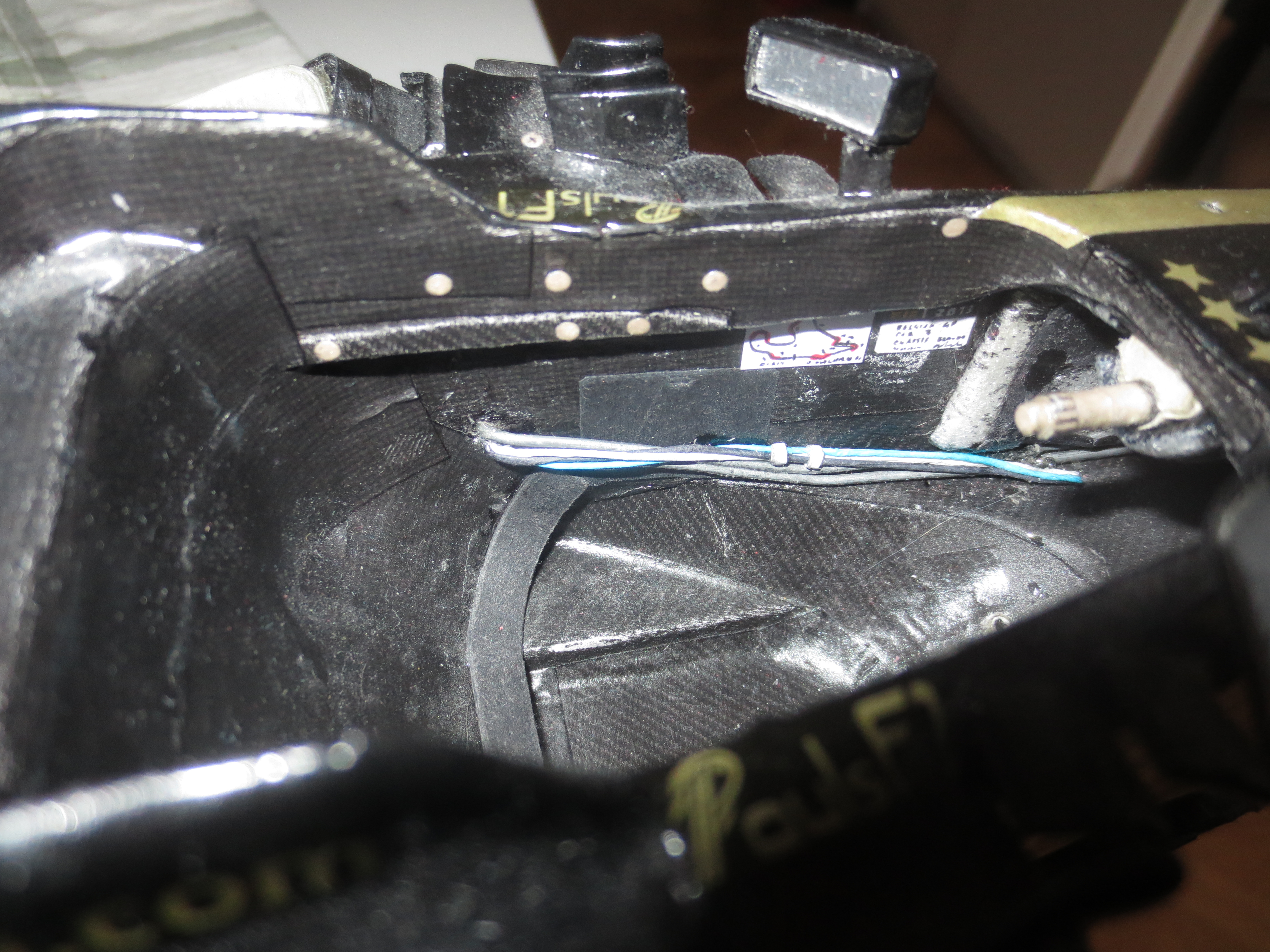
A view into the chassis with removed seat and steering wheel. At the bottom, you can see the fire extinguisher, right handed the fire extinguisher switch as well as the ignition switch are mounted. At the left hand side, the brake bias lever is mounted.
Just the seat straps are missing – but it’s actually hard to find suitable straps with the right colours and fabric.
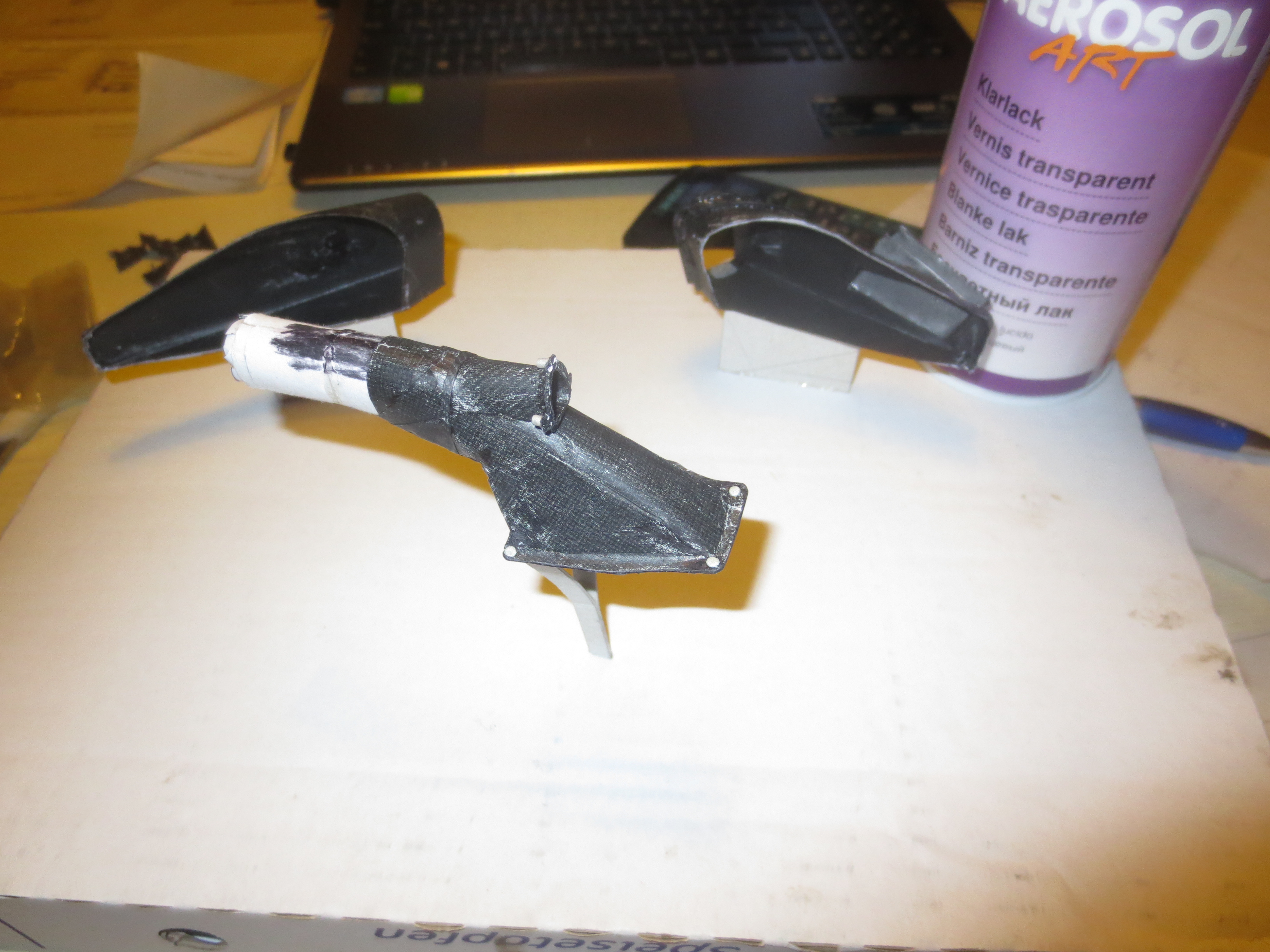
That are the raw exhaust pipes. They consist of a steel wire inside and a thick paper cover (many cylindrical layers). Before painting, the whole structure is covered with a thin layer of glue and sanded down to get a clean surface. The pipe which is sticked on the actual pipe is the helmholtz resonator. It simply provides a steady exhaust gas flow to get a nice blown floor. For an exact description of the effect, just google. It’s basically pretty simple.
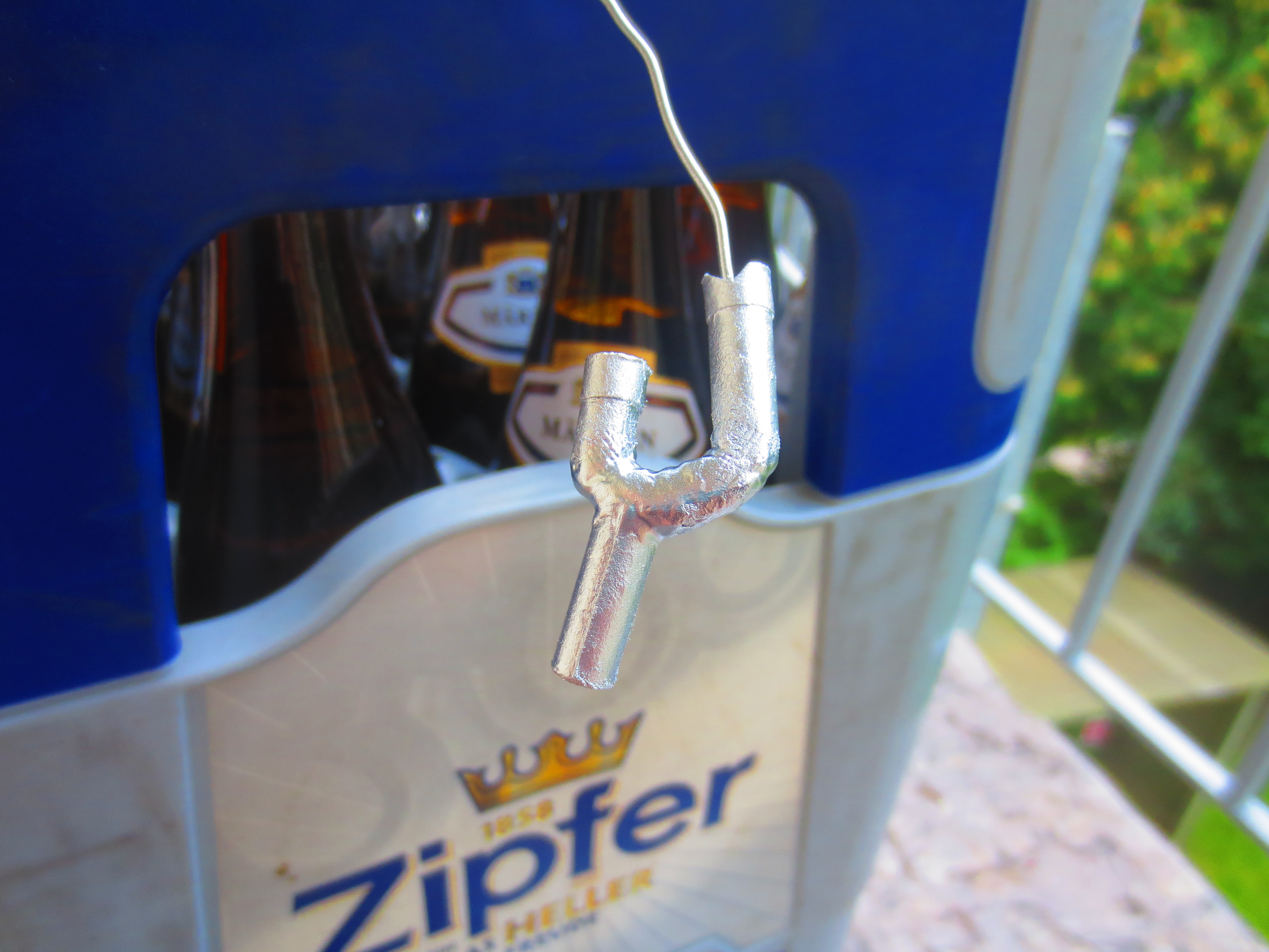
The right hand exhaust pipe during the painting process. The left and the right pipes are a little different due to the different space conditions in the side pods (oil radiator right handed, water radiator left handed). The paint jig (beer crate and a steel wire) is a bit unorthodox, but it’s simple and it works. 🙂
The right hand exhaust pipe in the side pod. It’s not fixed yet, as the lacquer is still curing. But somehow in this position it will be later on. The packaging of these cars was already quite tight, but not really comparable to the current generation of hybridcars.
The left hand side pod without its exhaust pipe. But the feeding lines for the water radiator are fitted.
Something is going on at the front of the chassis. It’s fully packed with brake fluid reservoirs, some gauge instruments and some electronics. Clearly visible, the pitot tube (air speed) at the top and the roll sensor at the bottom.
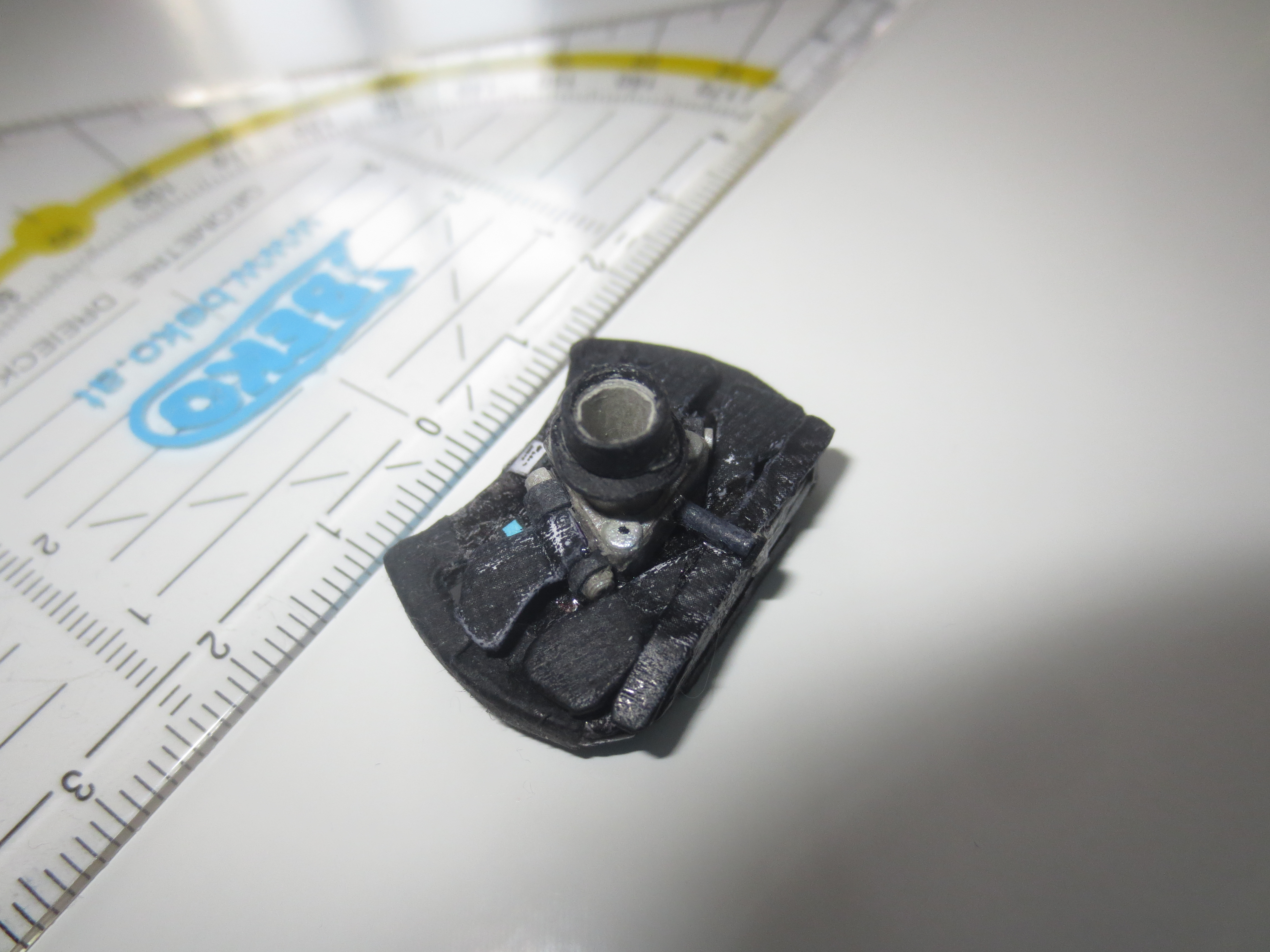
That’s the roll sensor, nicely shaped.
To get an imagination on the size of all these elements… Note also, there’s a 1 € Cent coin (diameter 16.25mm) lying on the chassis.
To do list
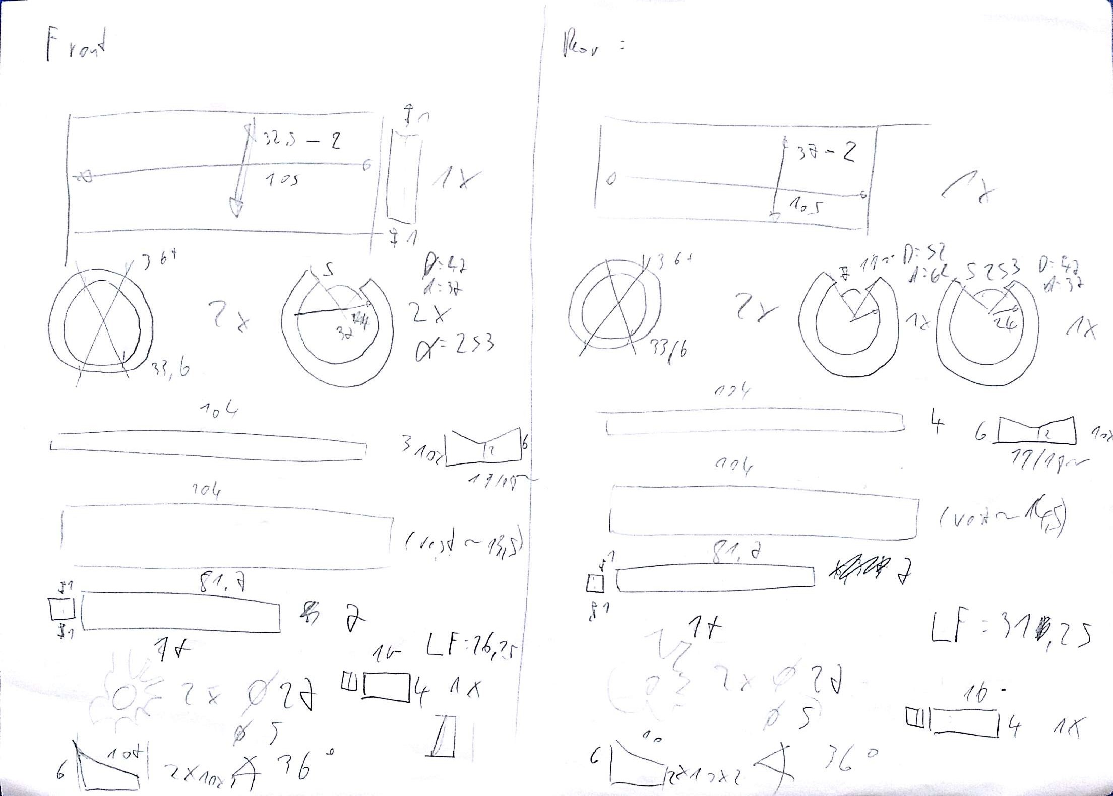
Rim instruction – all these parts are needed to produce a rim.
Lotus E21 construction report part 21
More to come in the next weeks…
Design start of cockpit internals, fitting radiators and finishing rear suspension components.
As uni stuff (exams) is coming to an end slowly, I’ve a bit more time left now and car progress will speed a bit up during the next time.
Over the last few weeks, I’ve done quite a lot of (more or less) small detail work on the car. First of all, I’ve found a suitable grid for protecting my radiators (metal grid with about 1mm mesh size). After fitting this to the rad ducts, I was finally able to fix the radiators to the car. A bit of detail work is still missing there, i.e. proper sealing, pipes, etc..
The next building site was the finishing of all the rear suspension components with clear lacquer. As I don’t have a proper paint shop (room), I had to wait for acceptable outside temperatures for lacquering on our balcony.
Next point are the cockpit internals. As I have to wait a lot during finishing and mounting the rear suspension, I need a site where I can build at and not touching the car a lot. So seat is more ore less done (picture series below), steering wheel (picture series below) is well on the way and some small bits such as “dashboard” (that’s the tiny bit at the drivers right hand side with fire extinguisher and ignition button on it) or belts are missing.
There’s not too much stuff missing at the car now. Front suspension, brakes, wheels and engine cover. Nevertheless, I expect finishing the car not before middle of autumn – maybe October.
Rh rad duct with fitted grid. Same proceedure at the lh side pod.
Rh side pod viewed from the front. The cooling duct for the electronics is outside of the grid. You can see it a bit at the lower face of the duct directly in front of the grid.
Rh side pod with fitted radiator. It will be a challenge to get the cooling pipes packed beside the exhaust system. There I made a little mistake. If you can call it a mistake… The exhaust manifold should be tilted a bit more outside the car. In my case, it almost touches the chassis. So there is very less space for the backflow pipe of the oil (rh) as well as of the water (lh) radiator. But I’ll find a proper solution to manage this little fail.

Rear suspesion stuff and barge boards finished (8 shiny lacquer coats for the barge boards, 5 mat for the suspension arms).
Here you can see my “seat shell tool” which I’ve designed entirely from 2d shapes. Beside, you can see the basic structural element of the seat shell in raw condition.
First, I layed up the basic structural element (which could be seen at the picture above), followed by two side and one central element.
Top view of the structural part of the seat in my seat tool.
Seat demoulded from its tool. At the sides it needs to be trimmed.
First fit of the raw seat shell.
Final fit of the raw seat shell with stiffening boudaries (red stripes).
Finished seat shell.
Back view of the finished seat shell.
Raw structural (base) element of the steering wheel – front view.
Raw structural (base) element of the steering wheel – back view.
Steering wheel base in the paint shop – or, as we have learned earlier, on the paint balcony. 😉
Placing buttons on the steering wheel.
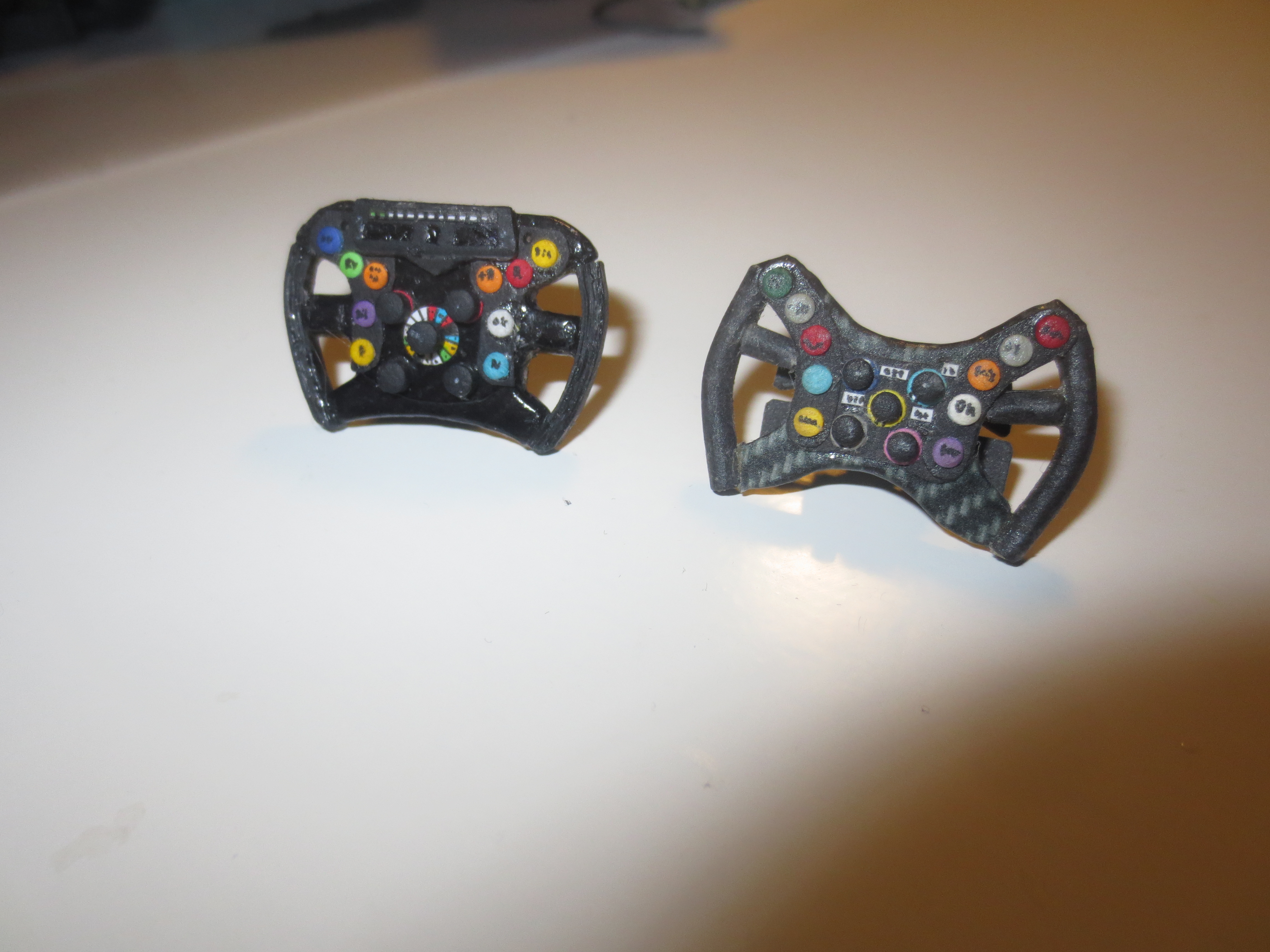
Comparison between the Lotus E21 and the Red Bull RB7 steering wheel. The Lotus one looks a bit more bulky as it has the display on the wheel and not on the chassis. The team appraoches differs in this regard. RB7 steering wheel has 73 part (as far as I remember), the Lotus one has 60 parts in its current stage (shift paddles and some details are missing).

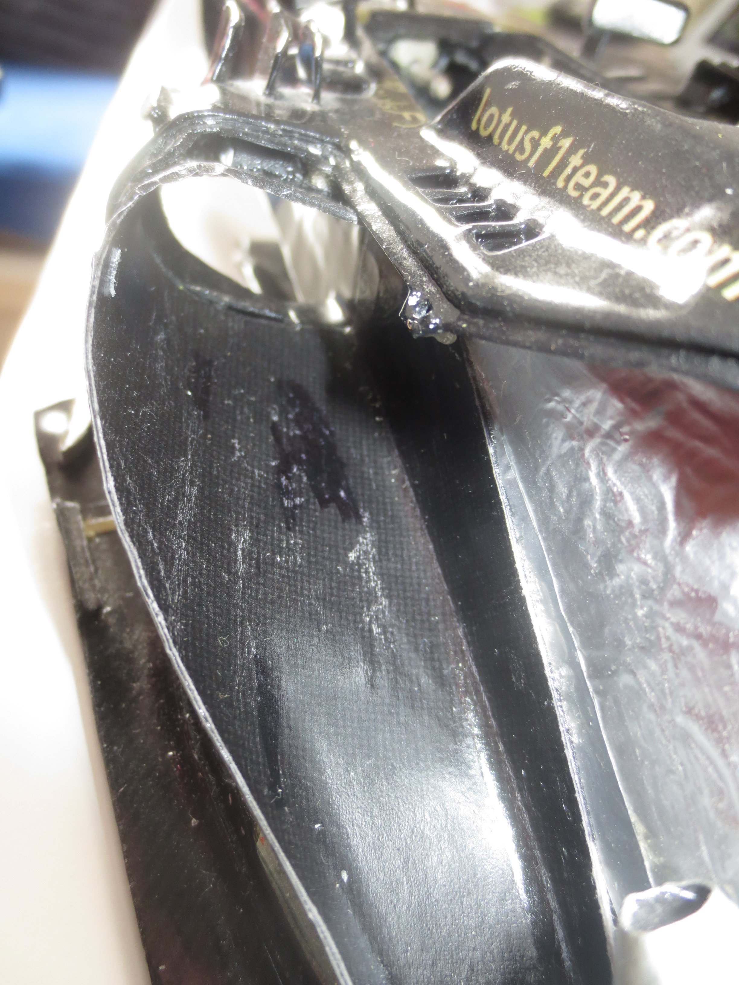
Rh cockpit side: emercency sticker, E21 chassis badge and some lines – I don’t like to describe all the lines (all electronics).
Lh cockpit side: FIA sticker, track sticker (guess, which one is it?) and again some lines (two hydraulics for brake and FRIC-S and some electronics).
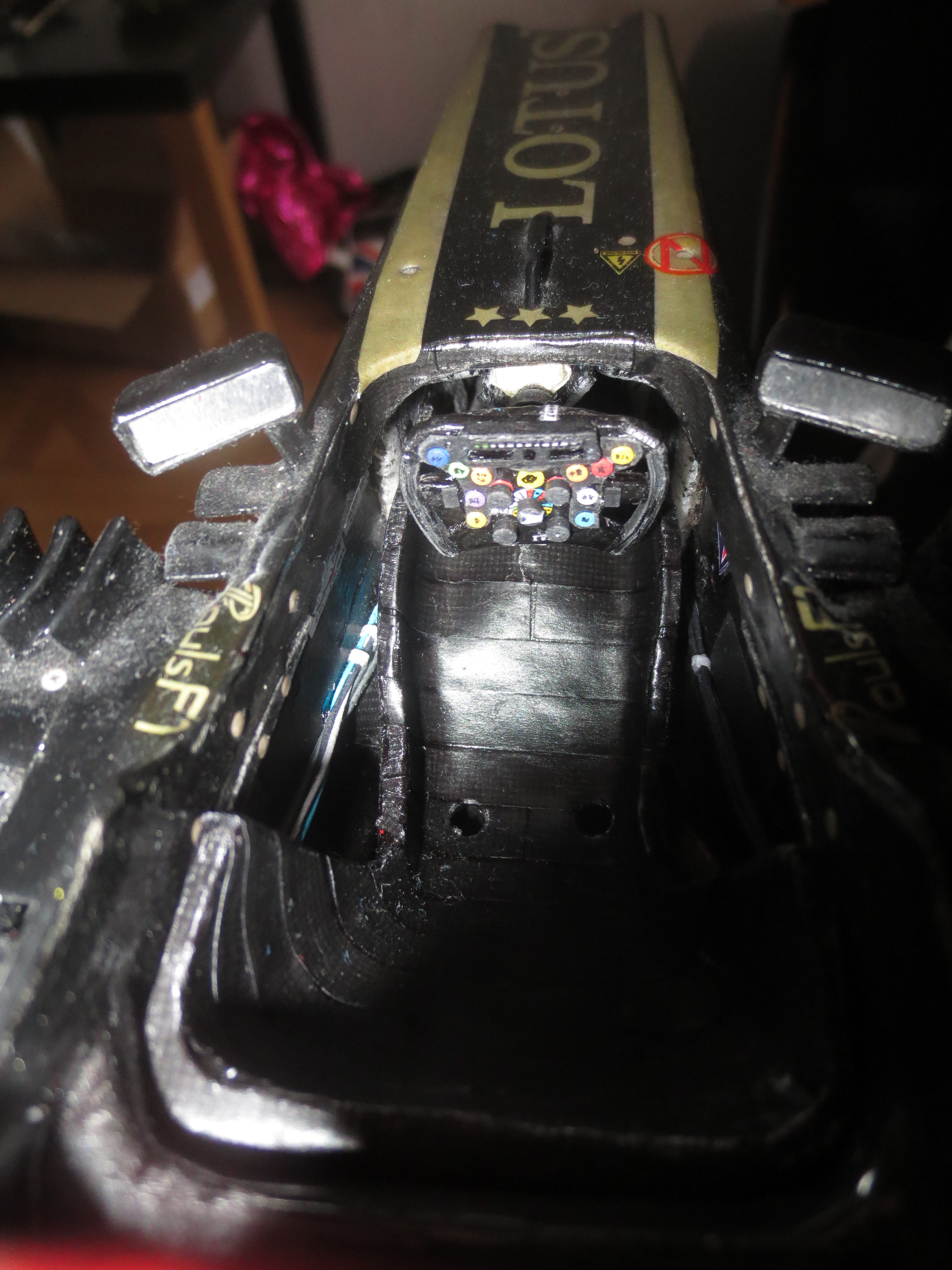
Cockpit view
PaulsF1 at Red Bull Racing
Hi all,
as you may know, in 2012 Rob Marshall, Chief Designer of Red Bull Technology, respectively Red Bull Racing, offered me a student placement job at the Formula 1 team. In August 2013, I started this challenge as a composite design engineer. Designing parts all over the car (RB10), I gained a very lot of experience in race car design and the work in a F1 team. In October 2014, I returned to Uni (Graz University of Technology), to finish my master studies in mechanical engineering. Here is a short video clip, produced by ServusTV which was part of a documentation about Austrian engineers in motorsports.
Cheers
©ServusTV
Lotus E21 construction report part 20
Summary report of December, January, February
Design start of front and rear suspension, manufacturing rear suspension and barge boards.
In December I started designing the front and rear suspension. Designing the suspension is one process, to get the suspension properly onto the car is a different step… The design of the suspension is based on the chassis/gearbox mounting points and the wheel position. The manufacturing of the rear suspension is almost done, just the pullrod is missing. The positioning of the upright relative to the chassis is one of the most essential points in the building process as it defines the position of the car above the ground in finished stage. For this reason I did a jig to position the upright correctly and connect it via the suspension arms with the chassis.
Also the barge boards are already manufactured and are awaiting the lacquering process (as well as all the suspension elements).

Front suspension layout: castor 3.5°, negative anti dive, king-pin inclination 8.5°, camber ~4°, track 146mm, minimal toe in, car inclination >1°. Some of the values are just guessed or given by wheel and upright geometry.

Rear suspension layout: king-pin inclination 19°, camber <0.5°, track 142mm, minimal toe out, static drive shaft inclination ~7°.

Rear upright structures beside the drawing. This structure is built from 0.5mm cornflakes card and later covered by 0.3mm silver card. Stiffness of the uprights is the essential property.

The finished lh rear upright (25.3mm x 19.5mm x 5.7mm).

Rear top wishbone – note the different fibre directions and weave styles.

Rear bottom wishbone – also note the different weave styles. The safety rope to stop the tyre from firing away from the car in case of an accident is placed in the backward arm and covered by a carbon cover (that’s the area with the different weave style).

All rear suspension parts (pullrod is missing) are waiting for getting lacquered.

The rear suspension in an early stage. At the top WB the structure can be seen, at the lower one, the metal wire can be seen which stiffens up the whole thing.

Rear suspension in a late state.

Jig to position the rear upright.

Barge boards.
Lotus E21 construction report part 19
Slowest progress ever…
Redesign of cooling ducts, finishing airbox, starting with electronics design and fitting process of the radiators.
There was a little progress over the summer since the last post. My intended finishing date for the car was something about in spring 2017, but with the current progress rate it could move into the summer. 🙂 But one after the other:
- I finished the redesign of the side pod cooling ducts. I did a design, when I built the monocoque back in autumn ’13, but in spring this year they proved to have a wrong size and position to fit the radiators (collisions with floor and exhaust end pipe). So, after the redesign they look fine, but it’s still a huge challenge to manage this tight packaging. I see more problems coming when designing the engine cover. 🙂
- Quick note on the airbox: All done, lacquered, fitted and sealed. No problems at all.
- A few weeks ago, I started with the electronics design. The electronics are fitted in the side pods each below the radiators, below the drivers seat and at the front of the monocoque. The rh side pod is already filled up with just missing out the cooling duct for one of the boxes. Btw – all electronics data are free available at mclarenelectronics.com – thanks MES for that!
- At the mo, I’m fighting to get the radiators properly fitted to the ducts.
Lh side pod duct – this duct houses the water radiator and the gearbox oil radiator. The gills in the side pod top face helps to get the hot air away from the radiator.
RH side pod duct – this duct houses the engine oil and the ERS radiator. At the very front of the duct you can see another duct which taps off a bit of air to cool the electronics that are housed below the duct. The big duct at the end of the main duct is for the ERS radiator. This will be better visible in a picture below.

Here you can see the finished radiators. At the front – engine water and gearbox oil, at the back – engine oil.

LH side pod with fitted radiators. You can see very good, how close the exhaust manifold is positioned to the cooler.
RH side pod with fitted radiator. Still a collision of the drain pipe and the exhaust manifold…
Top view of the car with fitted radiators. Against this view looks like, the radiators do not overhang the floor (which exploits the maximum width of 140mm). With fitted engine cover, the width should be 138mm.
Airbox is waiting for getting lacquered…
Airbox is waiting again – this time for getting fitted to the car.
Nothing to wait any more for the airbox. Fitted to the car and sealed off.
The electronics in the RH side pod. Also the ERS radiator sitting behind the electronic boxes is well visible. I could start to explain which box is what, but that would be too much I guess. Also notice all the live locks to fit the engine cover. Zoom in for details…
