
Lotus E21 construction report part 13
Engine Manufacturing
Over the last few weeks I, was working on the RS27 Renault engine. In the meantime it’s all done except the fitting bolts to the chassis. The engine has something around 700 parts in its final stage.
The engine is much more detailed then the one at the RB7. As you might know, the Lotus E21 and the Red Bull RB7 have the same engines with just a few minor visible improvements. At the RB7 I haven’t built a throttle hydraulic unit or the injection system was much more trivial. Also the engine block as well as the pick-up points for the monocoque and the gearbox should be a bit more stiff and rigid. All in all, an expected overall improvement of the engine.
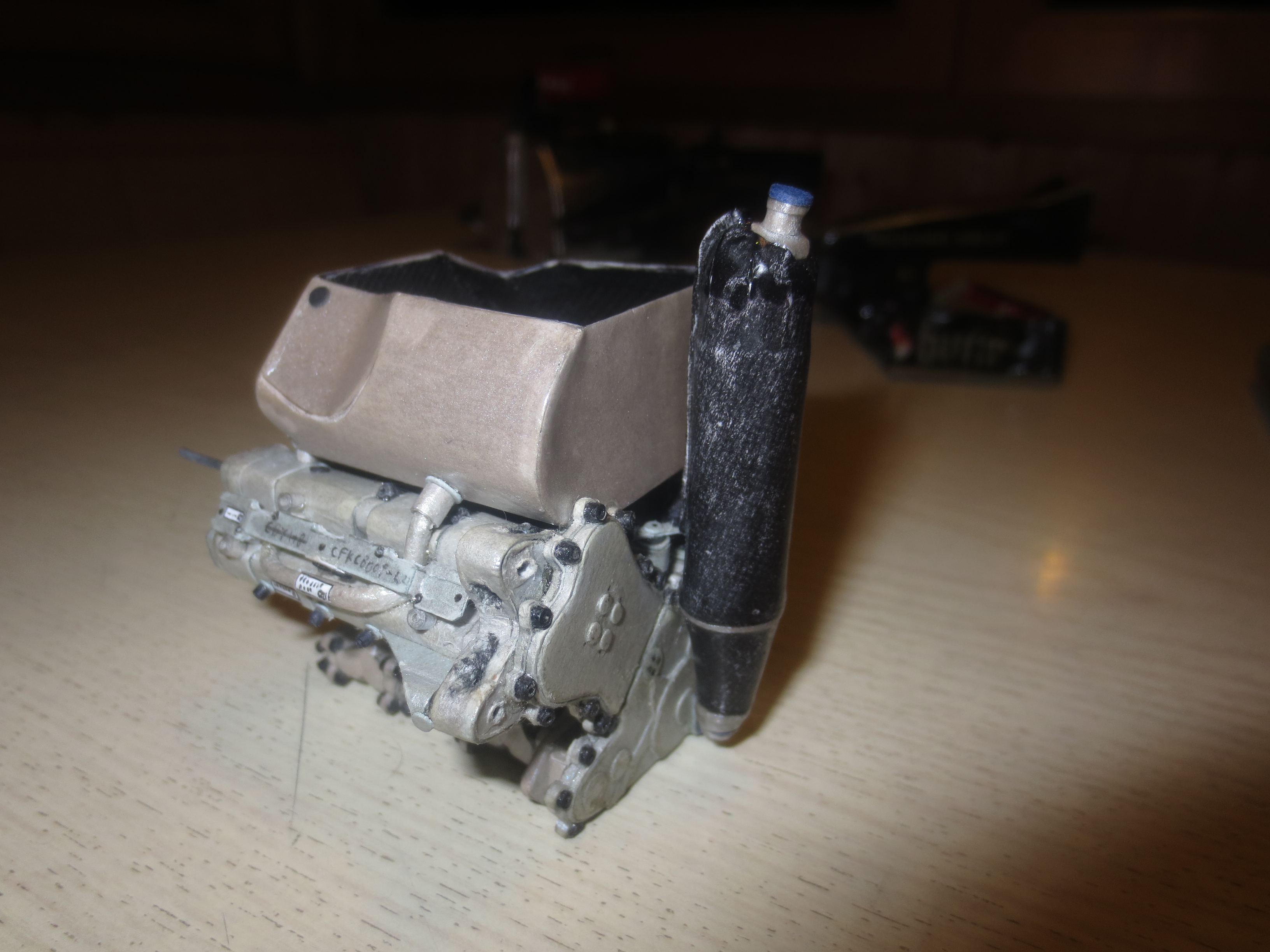
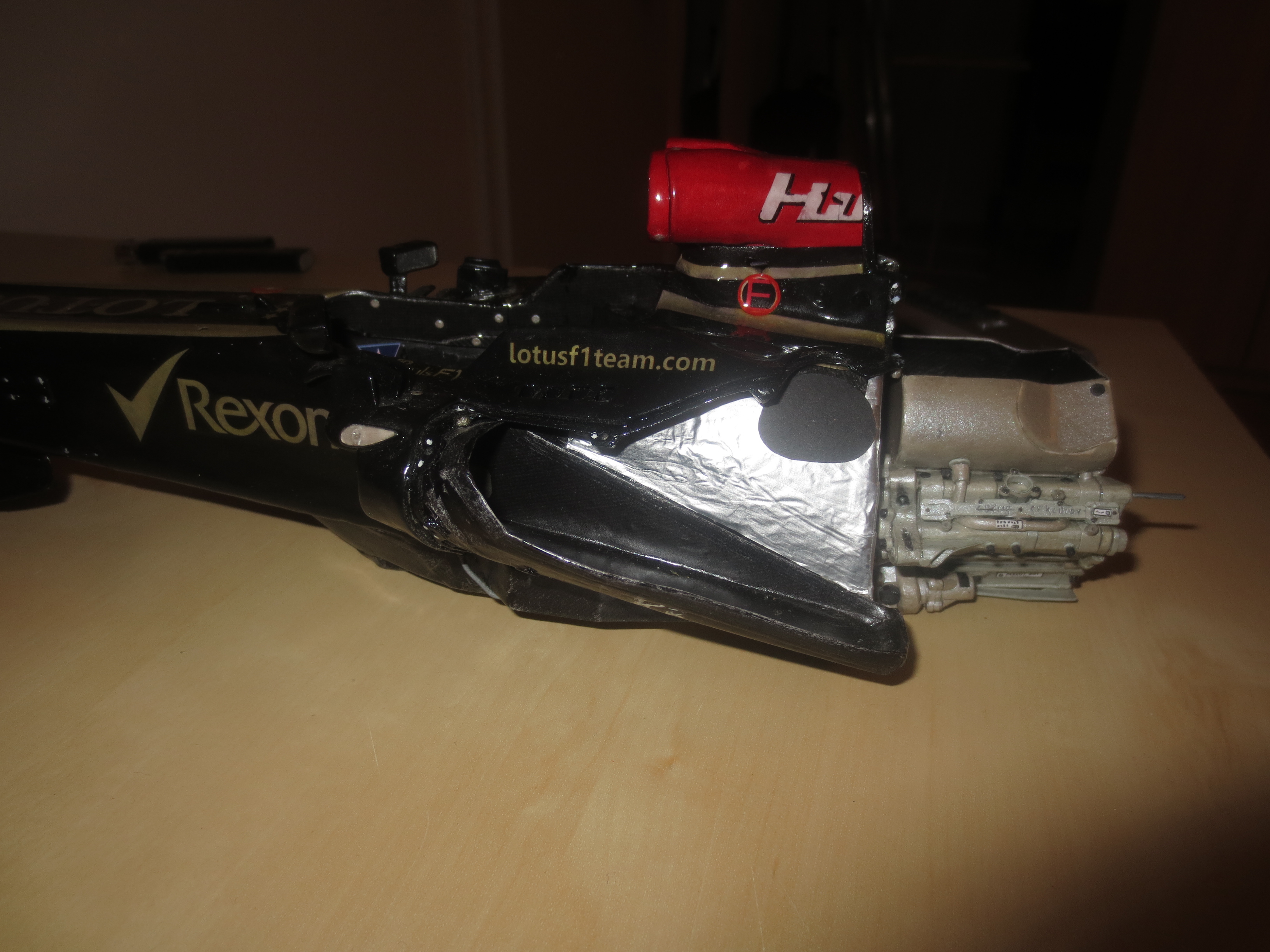
The Renault RS27 engine in its current state, viewed from the right front. You can see the carbon fibre moulded oil tank very well. There is a cutout in the rear wall of the monocoque to accommodate the oil tank between the chassis (fuel tank) and the engine. The oil itself is cooled by the radiator in the rh side pod (temp. approx 90°C – 95°C).
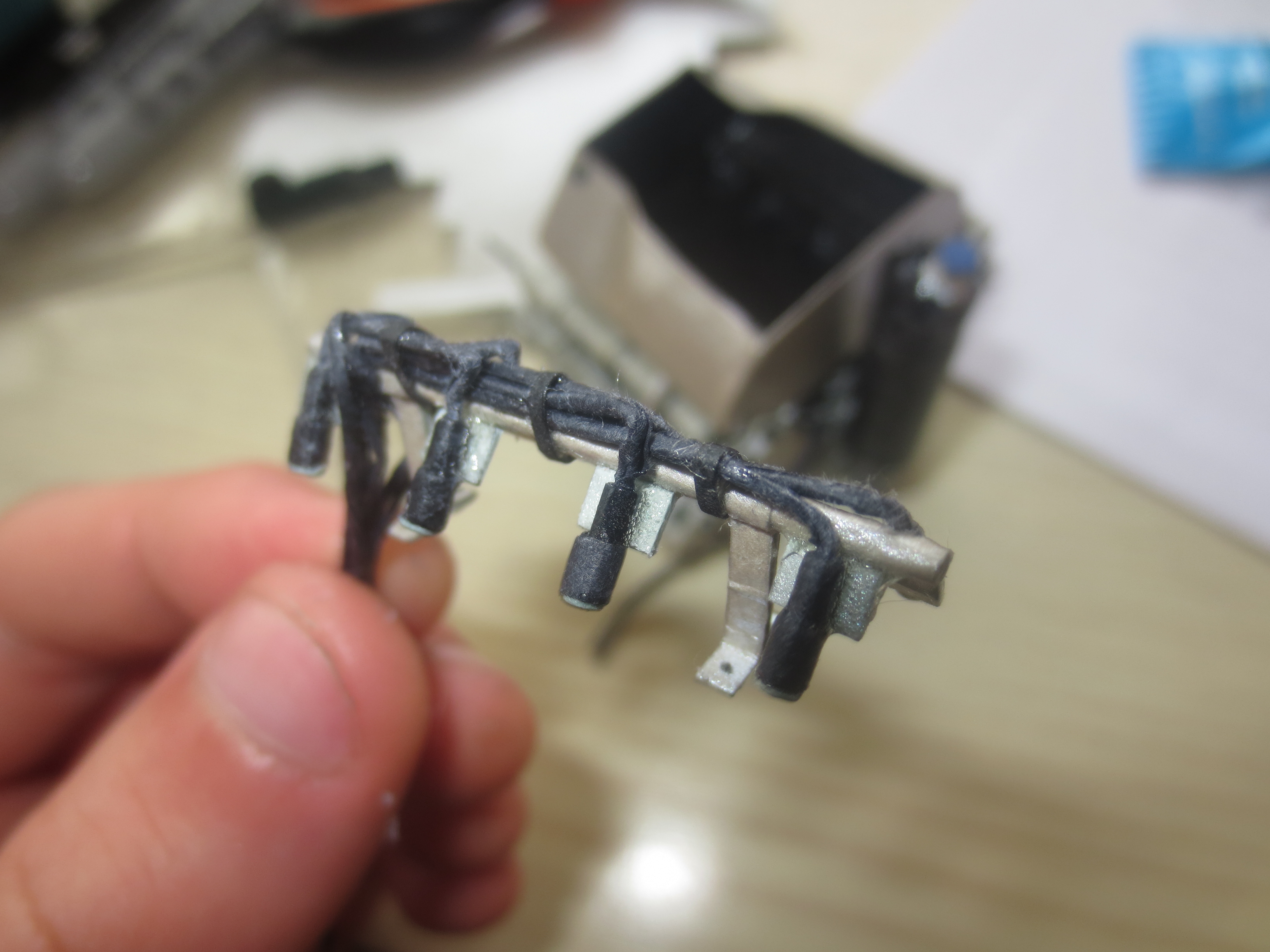
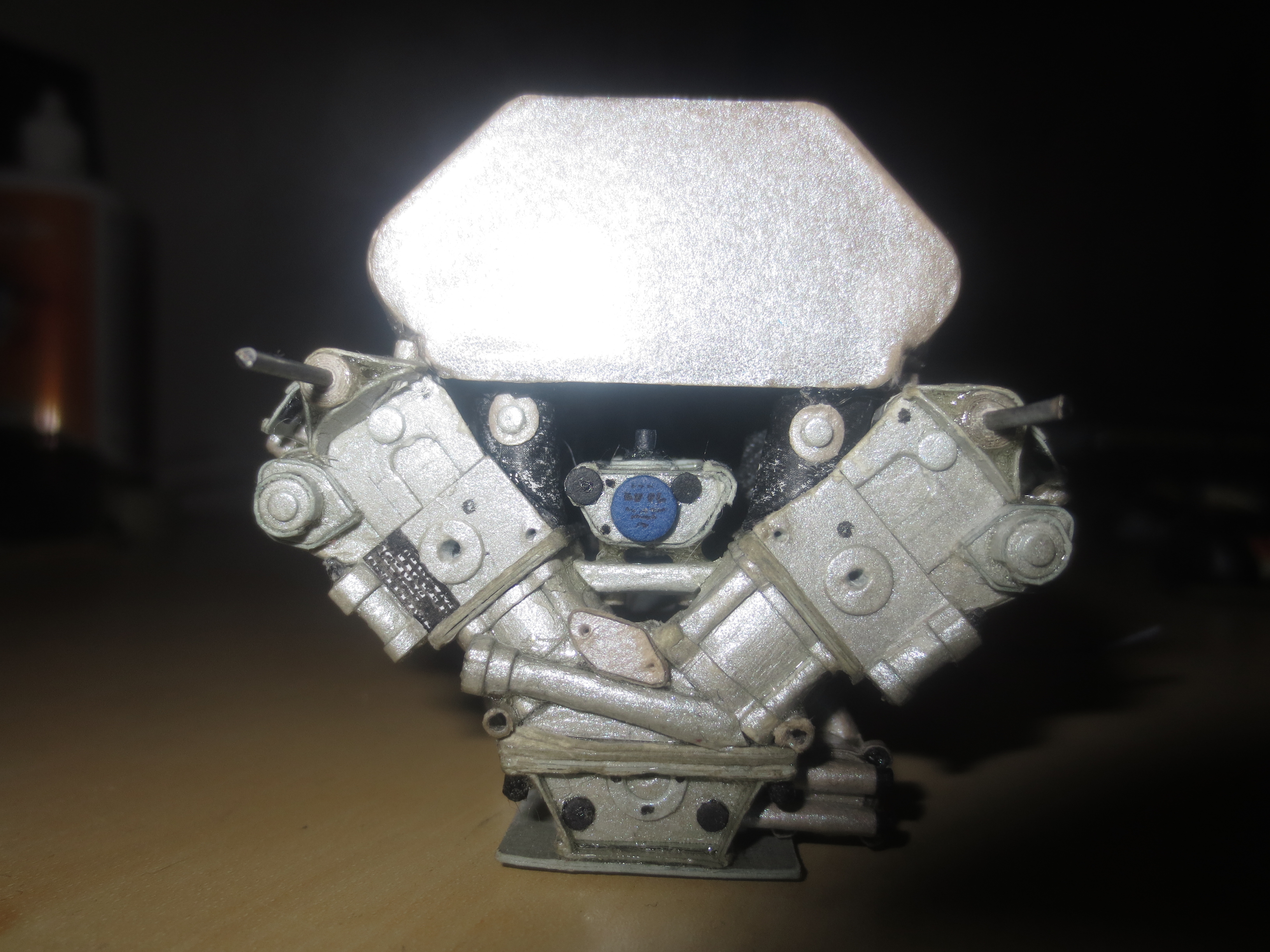
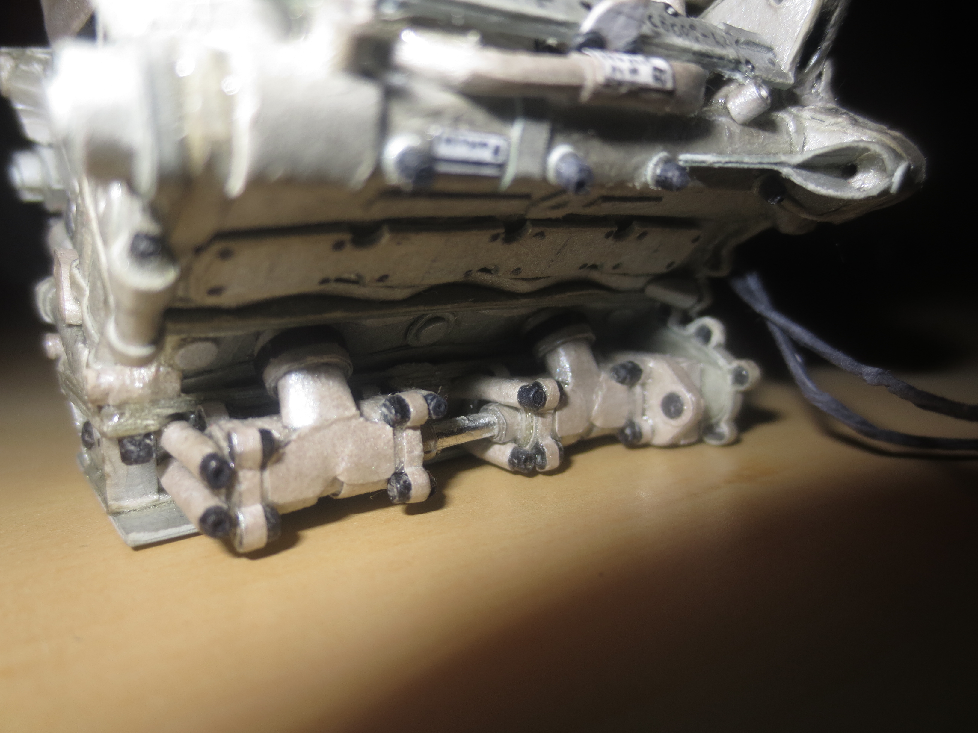
The part of the injection system which is located within the engine manifold. You can see the frame where the injectors sit on which inject the fuel under a pressure of 100bar into the inlet cones. The current 2014 F1 engines have direct injection with a pressure of 500bar. Direct injection saves fuel compared to a conventional injection system.
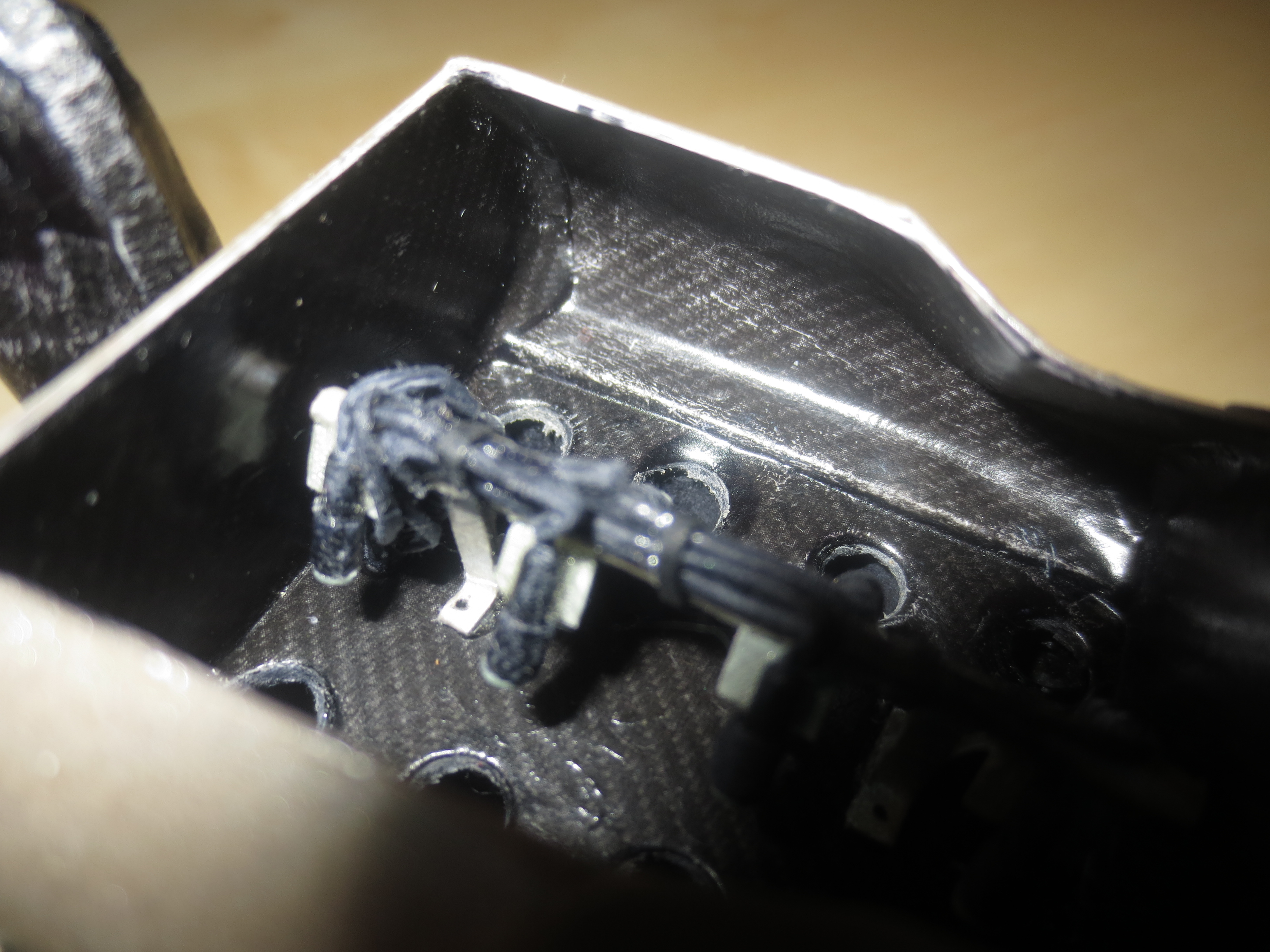
A view into the engine manifold with mounted injection system. I took some design borrowings for the injectors from older Renault engines as there were no pictures available from the RS27. On a YouTube video, published by Renault Sports F1, you can see a few bits of the system of the 2011 engine (on the test bench).
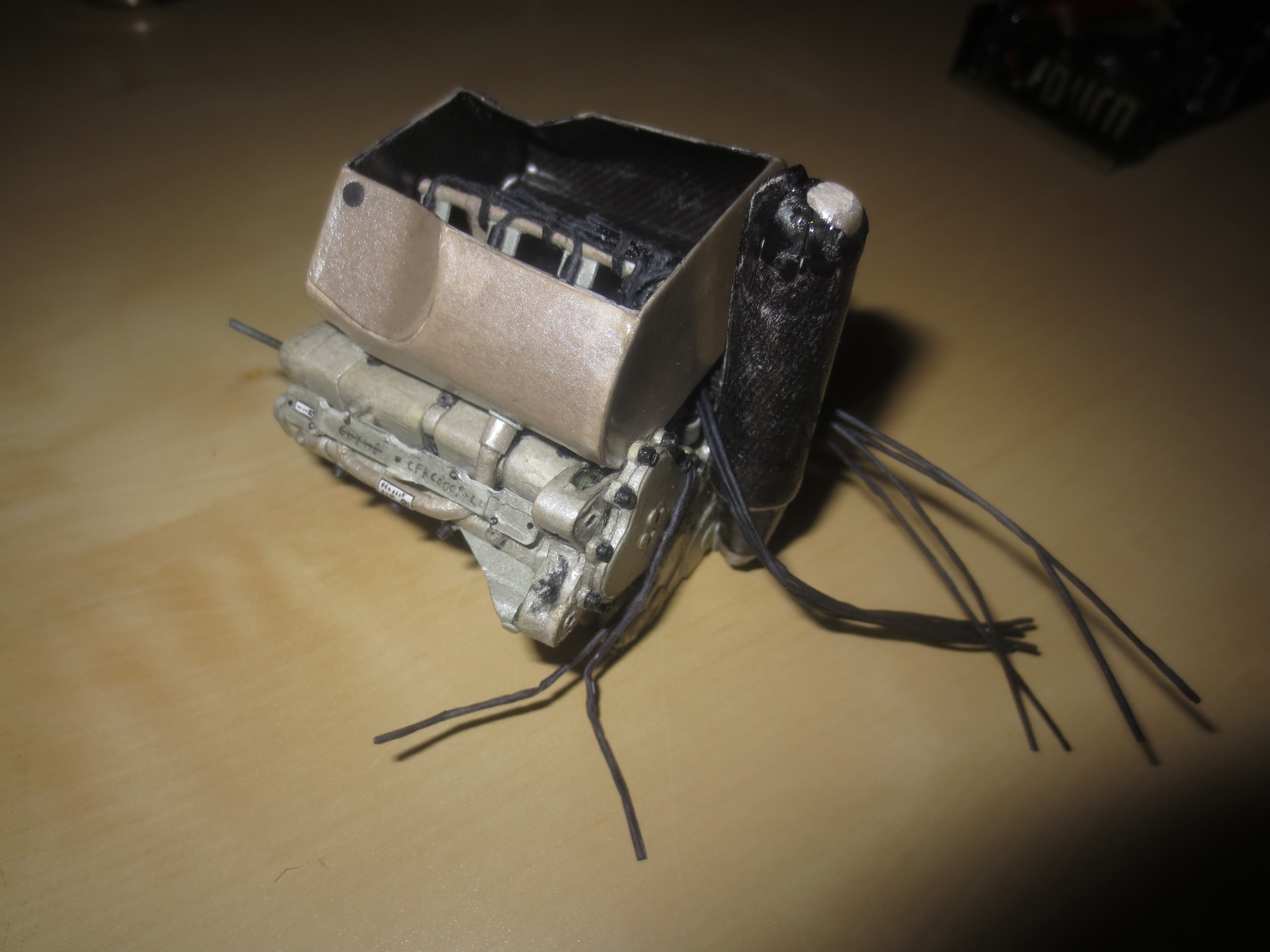
During the transportation back to Graz, the oil filler came off the oiltank (top of the tank). I’ll redo it before fitting the engine to the car. The two lines you can see coming from the inside of the V to the rh side of the engine are for the throttle control and will lead into the ECU (Engine Control Unit).
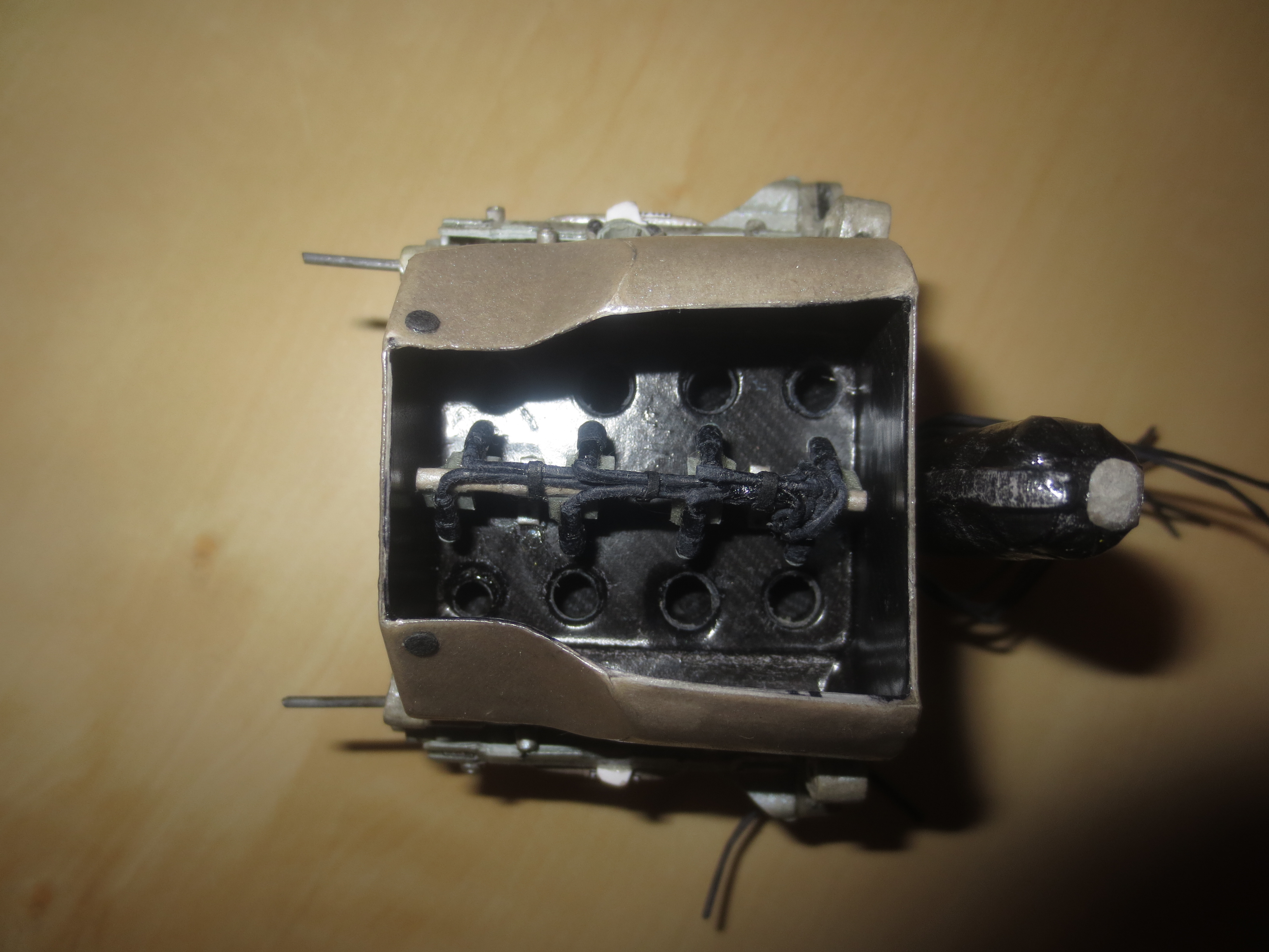
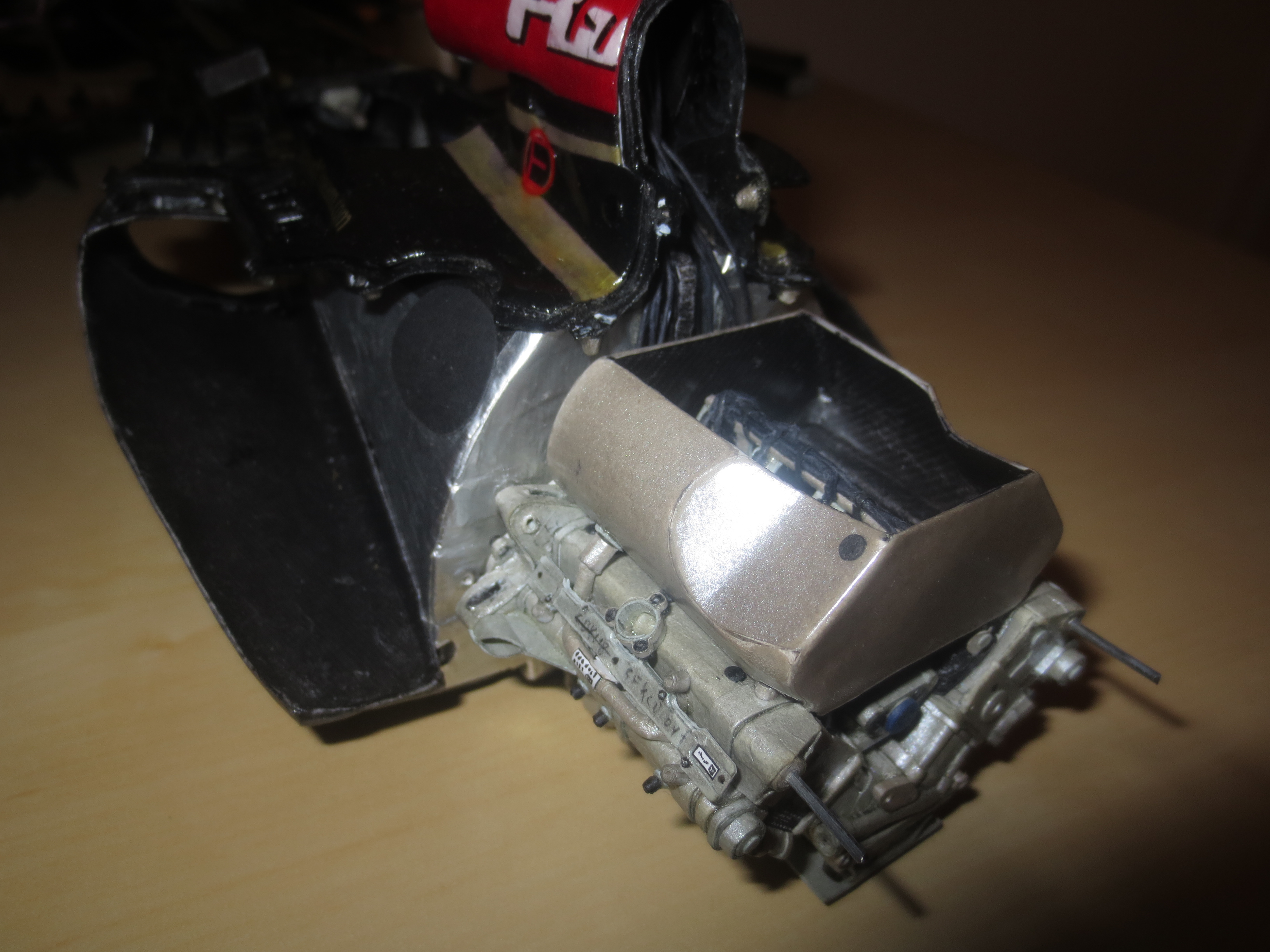
The RS27 engine from the top. The inlet manifold, which is fed by the airbox, is a CFRP item with a heat protection layer on the outside to prevent the air for the combustion process getting hot due to the engine/radiator heat.
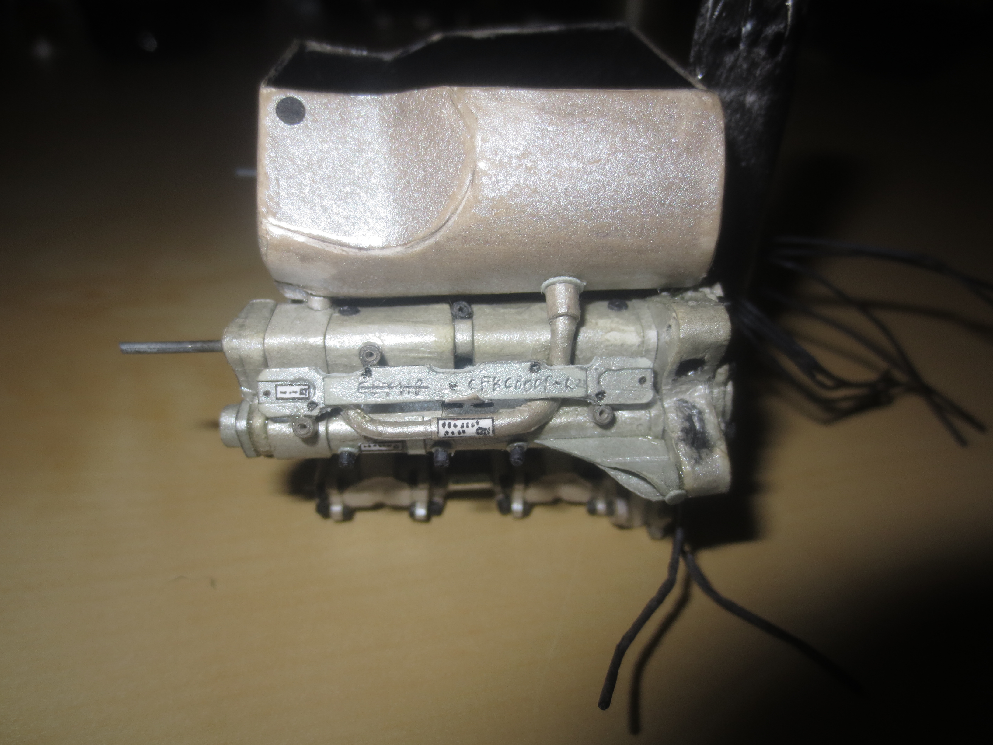
Cam(shaft) cover at the rh side. I’m not 100% sure what this line is for, which leads into the manifold. But I expect it to be the supply for the pneumatic valves. Even if they should work passively, I’m sure, there are some losses during a race and you have to refill the chambers of the valves.
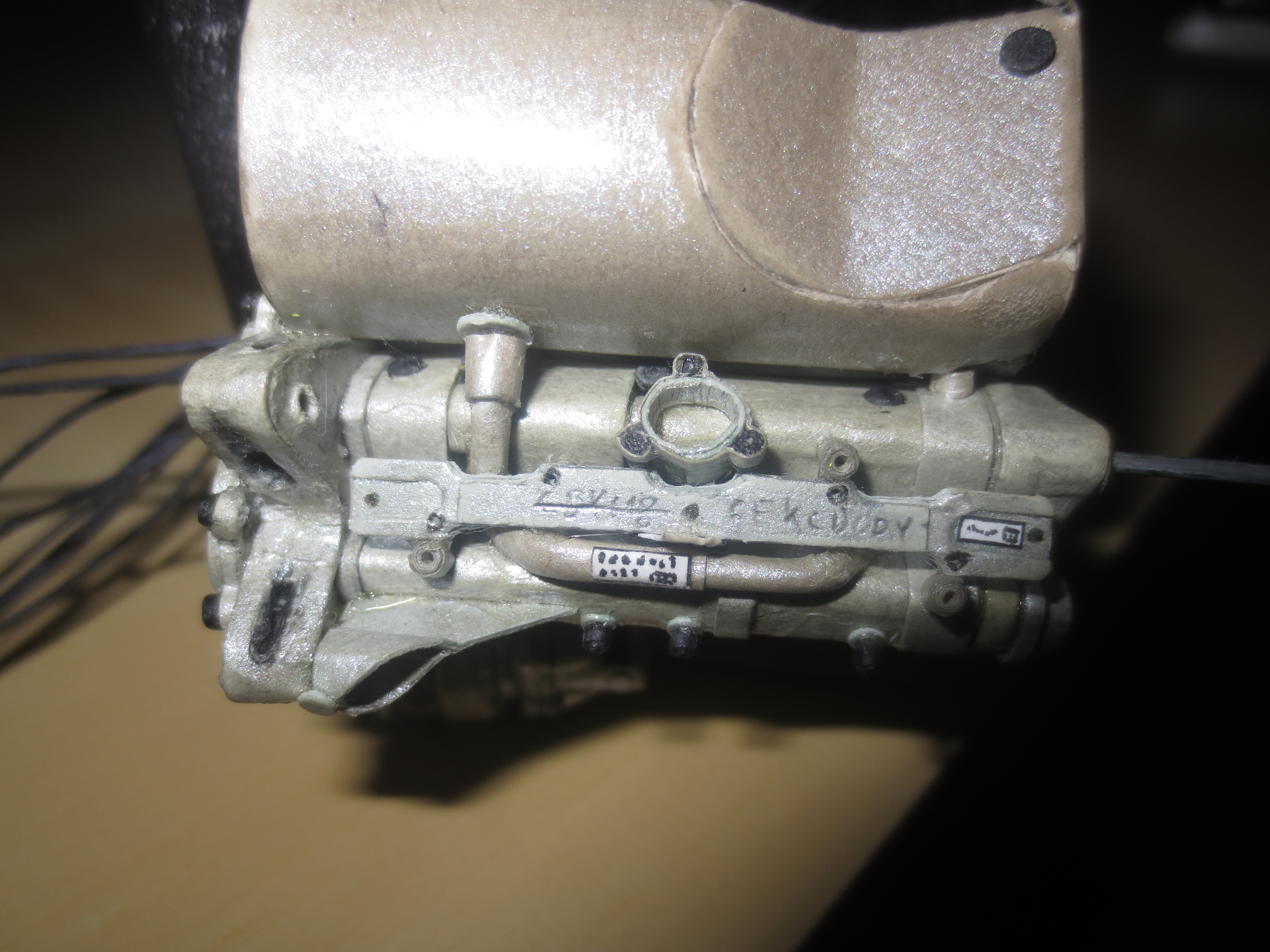
Lh side cam cover. Same as the rh one, just with the additional water inlet.
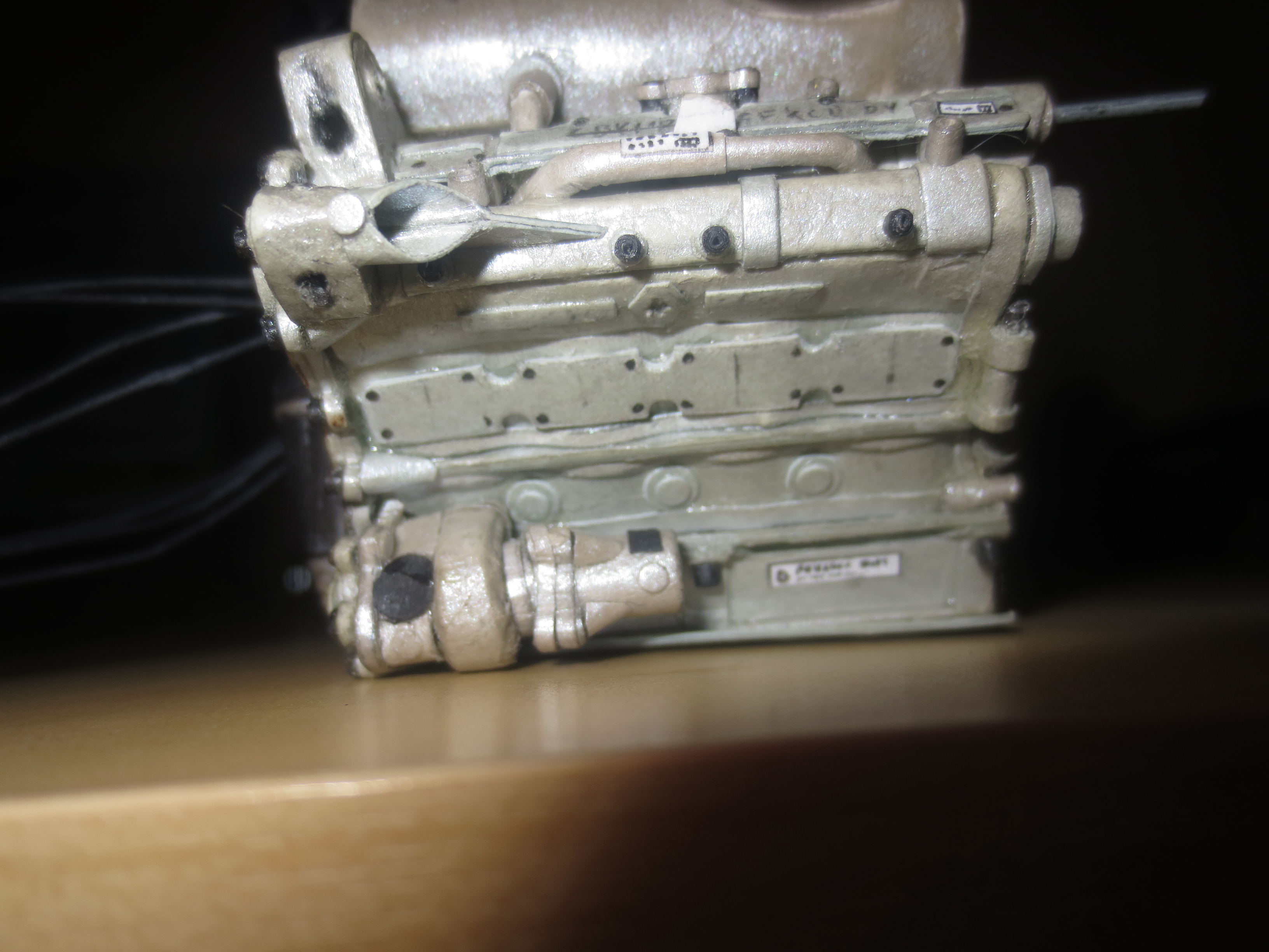
Rear view of the engine. You can see a part of the hydraulic throttle system. The two hyd connectors which supply the unit are missing. You can see also the two upper bolts to fit the gearbox. The four other bolts (which are required by the regulations) will probably be fixed to the gearbox.
Rh side of the engine with the oil pumps being visible at the bottom of the engine. There will also be the hydraulic pump of the rh side of the engine beside the oil pumps. But I will not mount it before fitted the gearbox as I think, the hyds pump is fixed to the gearbox.
Lh side of the engine. You can see the water pump (front) and the alternator (back). I’ll have to replace the alternator with a MGU I guess.
The Renault RS27 pre assembled to the chassis. Again you can see how small such an engine is. The dimensions length x with x height are 49.8mm x 71.7mm x 54.1mm.
Renault RS27 with chassis.
Lotus E21 construction report part 12
News on the Engine Manufacturing
This is more a tiny update just to keep the blog rollin. There will be more progress on the car when I’m back to uni finishing my mechanical engineering degree at the beginning of October. So look forward to that time!
As the engine is a fully stressed member of the car it’s very important to get a stiff and reliable connection between the engine and the monocoque as well as the gearbox. These connections I achieve with steel pins of 1.2mm diameter. On the real cars, the regulations dictates six M12 bolts to fix the engine to the monocoque as well as to the gearbox. Regulations around the engine cover bore, distance between cylinder axes, crankshaft height, bank angle, CoG, etc. With a bit of understanding of some engineering subjects and this data, it’s not that difficult to redesigned this engine from paper. It’s actually a bit like reverse engineering.

Current state of the car. At the left hand side of the car, you can see the water cooler and gearbox oil radiator, rh side is the engine oil as well as the KERS radiator. Between the engine and the Monocoque you can see the engine oil tank which catches about four litres of oil.

It’s again and again very impressive, how tiny the V8 engines were. Not to speak from the current downsized V6s. In the Le mans cars, the engines are often equipped with an additional brace as they are too weak to work as a fully stressed member.

Rear upper engine stud. This stud is fully integrated into the engine structure and picks up the upper gearbox mounting point.

Engine manifold. Fuel injection system and air filter will sit in here in a few weeks time.

The water pump at the lh side of the engine. There is another ancillary item going to sit behind the water pump.

The oil pump on the lower rh side of the engine. Beside the oil pump, the hydraulic pump/manifold is placed. It’s not designed yet. The hydraulic system powers throttle, clutch, gearchange, differential, power steering and DRS actuator. The hydraulic linked suspension is a completely independent system.
